IEC 62446-3 Accredited
Type A Inspection Body
Discover the future of the energy sector with MapperX!
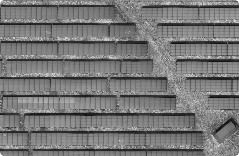
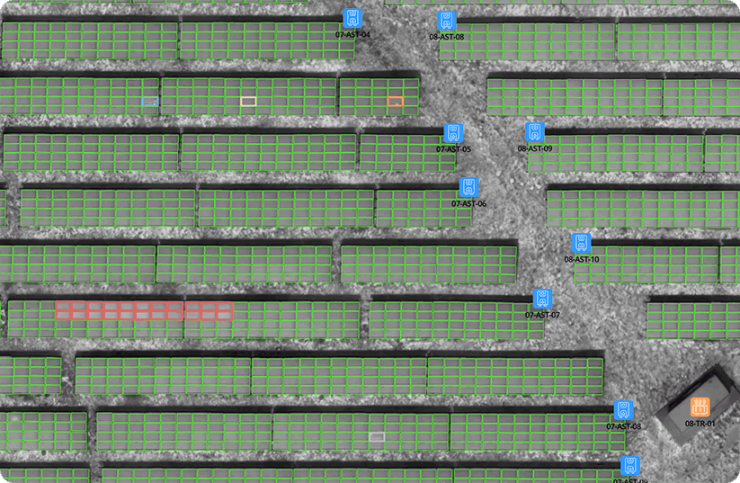
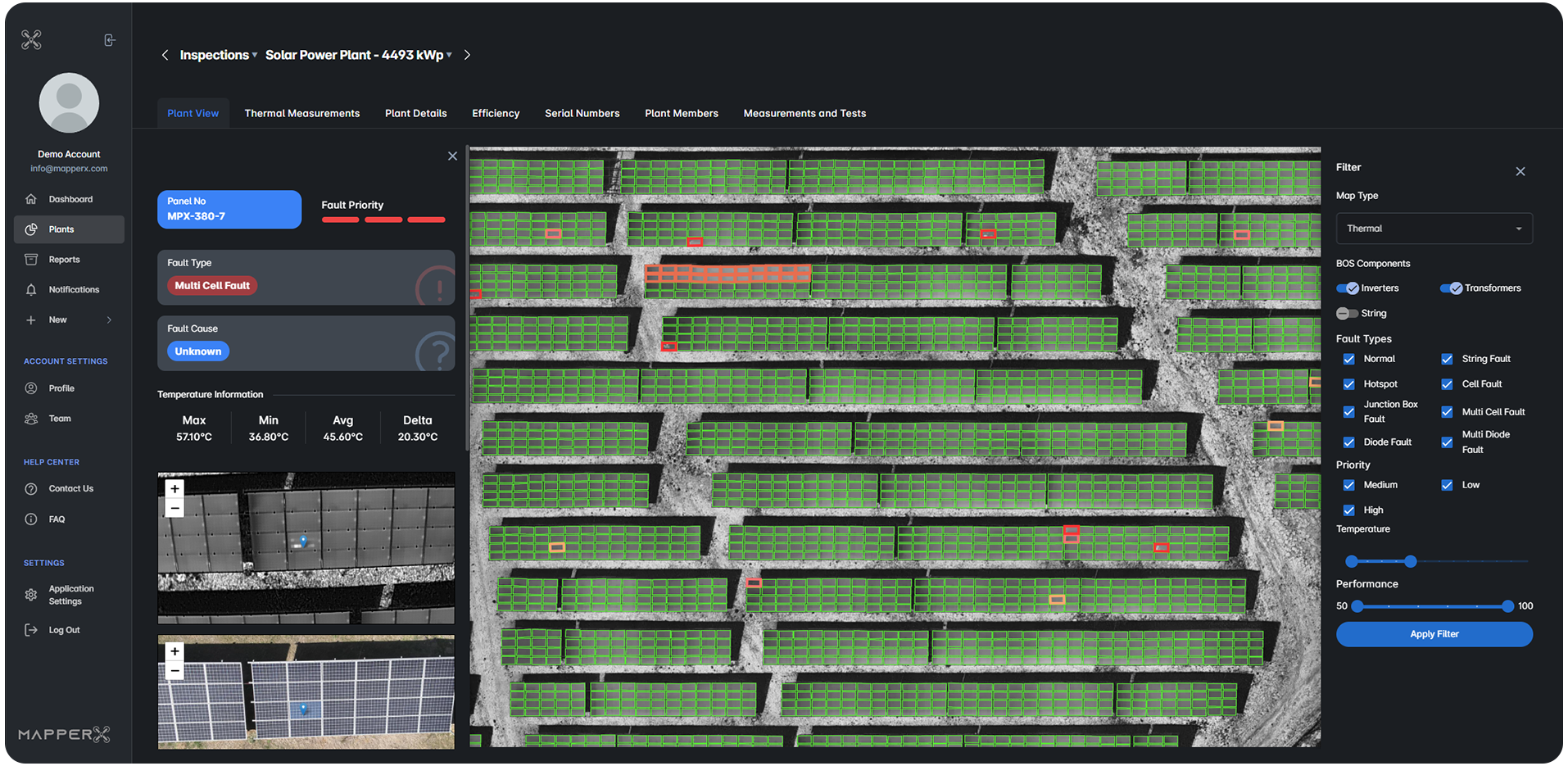
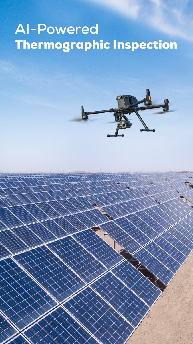
Conduct AI-powered autonomous thermographic inspections in solar power plants with MapperX. Create reports in compliance with IEC 62446 standards.
- Autonomously report results by detecting cell-based anomalies with AI-powered analyses.
- Perform fast and accurate temperature analyses of your panels by mapping with thermal drones.
- Gather and manage thermographic inspection operations of power plant components on a single platform.
Inspection and Examination
With Digital Twin Technology
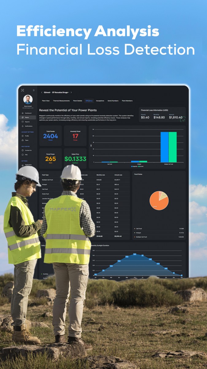
Create digital twins of your power plants with MapperX. Manage your inspection and examination processes on a single platform. The platform ensures speed, efficiency, and accuracy.
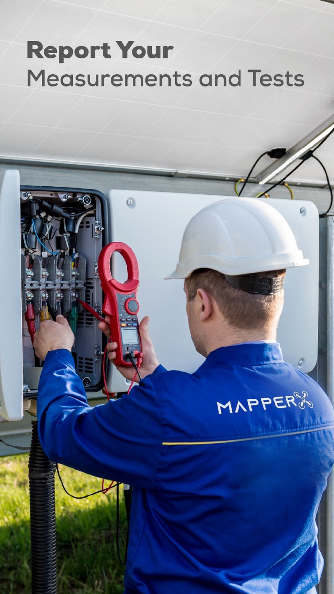
- Combine electrical measurements and tests in a single report.
- Digitalize your inspection processes to enhance sustainable efficiency.
- Optimize all your workflows and create unlimited reports.


Real-Time
Power Plant Management
Digitalize your maintenance and repair processes and perform predictive and periodic maintenance activities at your power plants. Ensure continuity in energy production.
- Reduce your costs by autonomizing your workflows.
- Manage your work orders effectively to increase operational efficiency.
- Record serial numbers quickly and accurately with MapperX.
Generate your reports instantly in any language.
The interface and PDF outputs are available in Turkish, English, German, French, Spanish, Chinese, Japanese, Portuguese, Bahasa Indonesia, Italian, and Dutch.

MapperX Compatible Drone Models
For detailed information on drone models supported by MapperX software and flight instructions, please visit our help center.

DJI Mavic 3T
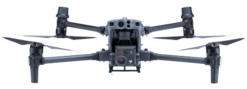
DJI Matrice 30T

DJI Matrice 4T
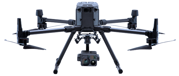
DJI Matrice 350 RTK + H20T / H30T
Pricing
Starter
- GSD: 10.0 ± 0.5 cm/pixel
- High Flight Level
- General Solar Module Inspection
- Low-Detail Analysis
- Detection of 2 Different Types of Anomalies
- BOS Components Module (Optional)
- Thermal and RGB Inspection
- Work Orders Module
- Panel Serial Number Scanning Module
- Efficiency Calculation
- Low-Detail Reporting
Professional
- GSD: 5.0 ± 0.5 cm/pixel
- Medium Flight Level
- Cell-Based Anomaly Inspection
Detailed Analysis - Detection of 15 Thermal and 5 RGB Anomaly Types
- BOS Components Module (Optional)
- Thermal and RGB Inspection
- Work Orders Module
- Panel Serial Number Scanning Module
- Efficiency Calculation
- Detailed Reporting
Enterprise
- GSD: 3.0 ± 0.5 cm/pixel
- Low Flight Level
- Inspection in Compliance with IEC 62446-3 Standards
- Comprehensive Analysis
- Detection of 15 Thermal and 5 RGB Anomaly Types
- BOS Components Module
- Thermal and RGB Inspection
- Work Orders Module
- Panel Serial Number Scanning Module
- Efficiency Calculation
- IEC 62446-3 Compliant Reporting
Start the Demo Now
Instantly explore a real solar power plant inspection, freely navigate within the platform, and discover our innovative features such as AI-powered analysis, autonomous reporting, and panel-based anomaly detection.
Frequently Asked Questions
1. What is thermographic inspection in solar power plants?
Thermographic inspection is a technique used to detect the temperatures of equipment in solar power plants. This inspection allows for early detection of potential faults and preventive maintenance.
2. Why is thermographic inspection important?
Thermographic inspection helps improve the efficiency of equipment in solar power plants. Early detection of faults and preventive maintenance can reduce operating costs.
3. How is thermographic inspection performed?
Thermographic inspection is performed using thermal cameras. The cameras detect the temperatures of the equipment, and this data is processed and reported by MapperX.
4. Does thermographic inspection damage the site?
Thermographic inspection is a non-destructive process and is applied without making any physical changes to your plant. It does not damage your site and helps maintain the safe operation of your plant.
5. Why is a thermal camera important?
Thermal cameras are used to accurately detect the temperatures of equipment in solar power plants. These cameras help with early detection of faults and preventive maintenance.
6. How is thermographic inspection reported?
Thermographic inspection data is processed by our software, and a comprehensive report is created. These reports are used to improve the efficiency of solar power plants and reduce operational costs.
The MapperX Help Center is a comprehensive documentation resource designed to make the MapperX platform easier to use and increase efficiency. It allows users to access the information they need quickly and effectively.
Follow the steps of region selection, route creation and data collection for the drone flight planning process on the MapperX platform. If you encounter any problems, you can contact our technical support team.
Blog
You can find articles about the latest technology news, sectoral developments and global energy trends regarding solar energy systems.
Get solar energy tips and information about the future of solar systems from our industry experts.
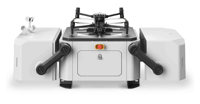
Drone Pilot Network
Get quotes from MapperX approved pilots and expand your operations globally.


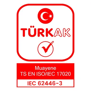

With our AI-powered software MapperX, we have automated thermographic inspection processes. Accredited under IEC 62446-3 as a Type A inspection body, our organization represents a first in the sector with this distinction.
![]()
MapperX is an AI-driven analysis and reporting software that enhances the efficiency of solar power plants while reducing carbon emissions. By digitalizing maintenance and repair processes, it increases operational efficiency, minimizes financial losses, and prevents fire risks.
Analysis, Management and Reporting Platform in Solar Power Plants.
© MapperX - All Rights Reserved.

