
Infrared Thermography
Infrared thermography records infrared radiation and estimates apparent surface temperatures using parameters such as emissivity and reflected temperature.
What Infrared Thermography Records
Infrared thermography records thermal radiation emitted and reflected by surfaces and represents it as temperature-related image data. In PV inspection, a thermal camera can help compare temperature patterns across modules, cells, connectors, cables, junction boxes, and other equipment when the acquisition conditions support meaningful interpretation.
The image does not directly show electrical current, insulation resistance, or mechanical damage. It shows surface thermal behavior. Electrical and physical conditions may create thermal patterns, but the relationship between the pattern and its cause has to be evaluated.
Absolute temperature is only part of the information. Relative differences between comparable components can be more useful when modules have similar irradiance, orientation, loading, and environmental exposure. Even then, comparison should account for reflections and viewing geometry.
A thermal camera therefore measures evidence, not diagnosis. The inspector still needs plant context, equipment knowledge, operating data, and appropriate follow-up methods.
How It Is Used in Solar Power Plants
PV thermography is commonly used to screen operating arrays for abnormal temperature patterns. Large plants contain many repeated modules, so thermal imaging can help identify locations that differ from surrounding equipment without electrically testing every module first.
A cell area may appear hotter than neighboring cells, part of a module may show a distinct pattern, or a connector or electrical joint may exhibit localized heating. Entire strings or sections can also appear different when their electrical operating state differs from nearby circuits.
These observations can guide maintenance teams toward specific modules, connections, rows, or circuit sections. The inspection is most useful when findings are tied to location data and can be compared with visible imagery, plant layout, string configuration, and monitoring information.
Thermography can also support post-event inspection after conditions such as storms, physical damage, or electrical incidents where thermal behavior is relevant. The scope should still be defined around the actual event rather than assuming that a thermal flight can identify every possible consequence.
IEC 62446-3 addresses outdoor thermographic inspection of operating PV systems and provides structure for equipment, environmental conditions, inspection procedures, personnel competence, and reporting.
What It Can and Cannot Establish
A localized hot cell or cell group can indicate that the area is behaving differently from comparable cells under similar conditions. The reason may involve electrical mismatch, shading, damage, interconnection behavior, or another condition. The thermal pattern alone does not determine which explanation is correct.
Bypass-diode behavior can produce recognizable module-level patterns under some operating states. However, assigning a diode fault solely from image appearance can be misleading if circuit condition, shading, module design, and electrical measurements are not considered.
Connection heating can also be significant. Increased resistance at a connector, terminal, fuse holder, cable joint, or other current-carrying connection can generate heat under load. A visible temperature rise can justify prompt investigation, but electrical verification and physical inspection may still be required to establish the cause.
Some faults do not generate a detectable thermal signature during the inspection. Others may only appear under a particular load, irradiance level, environmental condition, or intermittent operating state.
Thermography therefore has a clear boundary: it can identify thermal abnormalities, but it cannot prove every root cause or confirm the absence of all electrical faults. A normal image is not equivalent to a complete electrical test.
Aerial Thermography with Drones
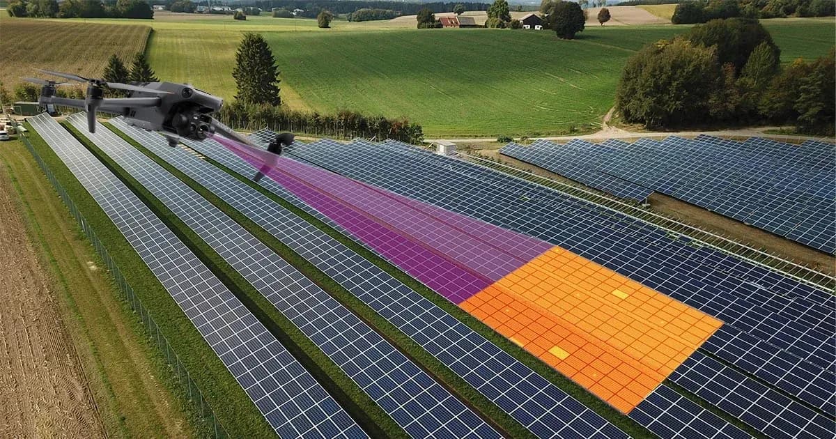
Drones allow thermal cameras to inspect large PV areas from above while recording the location of captured data. This can reduce the amount of manual movement required across long module rows and can provide a consistent overview of large ground-mounted installations.
Flight planning should be based on the required inspection detail. Camera resolution, lens, altitude, speed, viewing angle, and image overlap influence whether the target feature is actually resolved. A flight that is suitable for identifying module-level patterns may not provide enough detail for reliable cell-level interpretation.
Aerial acquisition also introduces geometric considerations. Reflections from module glass can change with viewing angle, and uneven terrain or tracker position can alter the camera-to-module relationship across the site. These effects need to be recognized during both flight planning and image review.
Location accuracy matters because a finding has limited maintenance value if technicians cannot identify the corresponding module or circuit on the ground. Thermal and visible imagery, plant layout, row identifiers, and flight metadata can help preserve traceability.
Drone inspection does not remove the need for ground work. Electrical confirmation, connector inspection, module replacement, and detailed physical examination still require suitable field access.
Assessing Electrical and Fire Risk
Abnormal heating can be relevant to electrical risk because resistive connections and some fault conditions convert electrical energy into heat. A connector, terminal, conductor, or module area that operates substantially differently from comparable equipment may deserve investigation before the condition progresses.
Thermal evidence can therefore support risk-based maintenance decisions. A pronounced or changing temperature abnormality may justify more urgent follow-up than a minor observation, but severity should not be assigned from temperature alone without considering load, environment, component type, and the likely failure mechanism.
Fire risk requires the same caution. Some electrical faults can contribute to ignition if sufficient heat or arcing develops near combustible material, but a thermal anomaly does not guarantee that a fire will occur. Conversely, the absence of a visible hotspot does not prove that no fire-related electrical hazard exists.
The appropriate response depends on the equipment, electrical condition, observed temperature behavior, surrounding materials, and follow-up findings. Thermography can identify conditions that deserve attention, but it should not be presented as a guarantee that fire will be prevented.
Maintenance teams should preserve the original observation and then verify the suspected condition using appropriate electrical or physical methods.
Conditions and Comparability
Irradiance is central to PV thermography because electrical loading and heat generation depend on the energy reaching the modules. Weak or rapidly changing irradiance can reduce thermal contrast or make one part of the plant difficult to compare with another.
Wind cools module surfaces and can suppress temperature differences. Strong or variable wind can therefore change the apparent thermal pattern even when the underlying electrical condition remains the same. Wind conditions should be recorded where they are relevant to interpretation.
Cloud movement can create rapid irradiance changes across a site. Images captured before and after a cloud passes may not represent comparable operating conditions, particularly when a drone flight covers a large area over time.
Module temperature provides additional context, but there is no single temperature range that defines acceptable inspection for every plant. IEC 62446-3 does not impose one universal module-temperature threshold across different installations.
Viewing angle and reflections also affect image reliability. Module glass can reflect the sky, surrounding structures, vegetation, the aircraft, or other thermal sources. An apparent hot or cold area should therefore be checked for geometric and reflective causes before being classified as an equipment abnormality.
Repeat inspections are most useful when these conditions are recorded consistently.
What Follows a Thermal Finding
A thermal finding should first be tied to a physical location and described without overstating its cause. The report can record the affected module, cell area, connector, string, or equipment item together with the observed temperature pattern and the conditions under which it was captured.
The next step depends on the type of observation. A suspected connection problem may require electrical measurement and physical inspection, while an unusual string pattern may lead to current, voltage, polarity, or continuity checks. A module-level abnormality may require comparison with visible damage, operating data, or additional module tests.
The inspection record should preserve thermal and visible evidence, location, environmental conditions, equipment used, and any limitations that affected interpretation. Areas that could not be inspected reliably should be identified rather than assumed to be normal.
Repeat inspection can be useful after corrective work or when the initial finding depends strongly on operating conditions. The purpose is to verify whether the thermal behavior changed, not simply to reproduce another image.
One thermal survey is not continuous monitoring, and thermography does not replace electrical testing where direct verification is required. IEC 62446-3 provides a framework for outdoor thermographic inspection of operating PV systems, but conformity, fault diagnosis, and maintenance decisions can require evidence beyond the thermal image.