
PV System Insulation Resistance Test
PV system insulation resistance test evaluates insulation between the specified live circuits and earth using a controlled test voltage.
What the Insulation Resistance Test Measures
An insulation resistance test measures how effectively conductors and energized parts are electrically separated from earth, exposed conductive parts, or other conductors that should remain isolated. In a PV system, the measurement can help assess DC cabling, junction boxes, connectors, string circuits, and other insulation paths included in the test scope.
The instrument applies a defined DC test voltage and measures the resistance of the insulation path. A high resistance generally indicates limited leakage through the tested insulation, while an unexpectedly low value can point to contamination, moisture, damaged insulation, wiring errors, or connected equipment influencing the measurement.
The result only applies to the circuit configuration and conditions present during the test. A satisfactory resistance value does not prove that every cable, connector, module, or enclosure in the plant is free from defects.
The test should therefore be treated as one electrical measurement within a broader inspection process. Its value comes from knowing exactly what was connected during the test and what electrical path the measured resistance represents.
Why It Is Performed
One purpose of insulation resistance testing is to identify unintended leakage paths between PV circuits and earth. Such paths can develop through damaged cable insulation, moisture ingress, contaminated enclosures, deteriorated connectors, crushed wiring, or other defects affecting electrical separation.
The test may also help investigate insulation alarms reported by inverters or monitoring systems. If a plant reports a low-insulation condition, measurements taken on progressively smaller sections of the DC system can help narrow the location requiring physical inspection.
Insulation resistance testing is commonly relevant during commissioning, after electrical work, and during defined periodic inspection programs. It can also be used after events or maintenance activities that may have affected cabling, junction boxes, connectors, or other insulation systems.
The purpose is verification, not performance optimization. Measuring insulation resistance does not increase module efficiency or recover production by itself. It provides evidence about the electrical condition of the tested insulation path.
Where several strings or sections can be isolated independently, comparative testing can help locate the circuit responsible for an abnormal result. This is often more useful than repeatedly testing the complete array without separating possible sources of leakage.
Why It Matters for Electrical Safety and Fault Location
Insulation separates energized conductors from parts that should not carry operating voltage. Deterioration can create leakage paths that affect protective functions, produce inverter faults, or expose conductive parts to conditions that require investigation.
An abnormal insulation resistance result can therefore be important even when the plant is still producing power. Continued operation does not establish that the insulation system is in acceptable condition. The significance of a measurement depends on the system design, measured value, circuit configuration, environmental conditions, and the acceptance basis used for the inspection.
For fault location, the system can be divided into smaller test sections when the installation design permits safe isolation. The technician may compare arrays, strings, cable sections, or equipment groups to determine where the resistance changes. That process can reduce the amount of equipment that needs to be physically examined.
The test does not identify root cause automatically. A low value might come from water ingress, damaged insulation, contaminated connectors, connected surge protection equipment, electronic devices, or the measurement arrangement itself. Physical inspection and additional electrical checks may still be necessary.
How the Test Is Carried Out
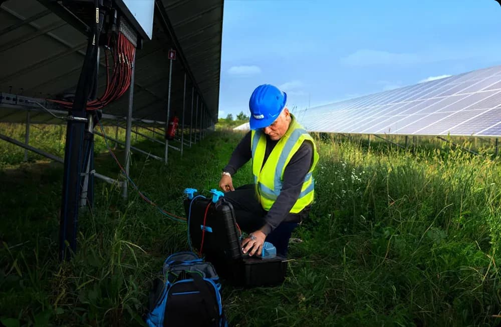
Before testing, the field team should identify the circuit boundaries and determine which equipment can remain connected. Inverters, monitoring devices, surge protection components, optimizers, or other electronics may be affected by an inappropriate insulation test voltage, so equipment documentation and the plant test procedure should be reviewed before the instrument is connected.
The circuit normally needs to be placed into the electrical state required by the selected test method. Isolation, verification of the circuit condition, and control of stored or generated energy should be handled by competent personnel. PV strings can remain electrically active whenever sufficient light is available, even when an inverter is switched off.
The insulation tester applies a specified test voltage between the conductors and the reference point defined by the procedure. Depending on the system and method, conductors may be tested separately or combined in a defined configuration. The selected voltage should come from the applicable procedure, equipment requirements, or acceptance basis rather than from an arbitrary value.
The technician should use an instrument suitable for the expected DC system voltage and test method. Leads, probes, connectors, and personal protective measures should also match the electrical conditions at the plant.
After the measurement, the circuit may retain charge from the test. The procedure should address discharge and verification before conductors are handled or equipment is reconnected.
Interpreting Results
Insulation resistance is affected by more than permanent defects. Moisture, surface contamination, temperature, condensation, and the total size of the connected circuit can influence the measured value. Two measurements made under different environmental conditions should therefore not be compared without considering those differences.
Humidity and recent rain can be particularly relevant on outdoor PV equipment. A lower value during wet conditions may indicate a moisture-sensitive insulation path that is not apparent during dry weather. That observation can be diagnostically useful, but the measurement still needs to be interpreted against the plant configuration and test conditions.
Temperature can also affect insulation behavior. For repeat measurements, recording environmental and equipment conditions makes later comparison more meaningful. A historical record without those conditions can make a normal environmental change look like electrical deterioration.
One measurement should not automatically be treated as a long-term trend. If condition monitoring over time is the objective, the same circuit boundaries, test method, instrument settings, and relevant environmental conditions should be recorded consistently.
An abnormal result should normally lead to verification before a specific component is blamed. Dividing the circuit, repeating the measurement, checking connections, and inspecting suspected areas can help distinguish an actual insulation defect from test setup or connected-equipment effects.
Records and Frequency
A useful insulation resistance record identifies the circuit or equipment tested, conductor configuration, test voltage, measured resistance, instrument used, date, and relevant environmental conditions. It should also state which equipment was disconnected or remained connected during the test.
The acceptance criterion should be recorded with its source or basis. A resistance result without the corresponding test configuration and acceptance method has limited value because the size and topology of the connected PV circuit affect interpretation.
Testing frequency should follow the plant's commissioning requirements, maintenance plan, operating history, equipment instructions, contractual obligations, and observed conditions. Additional testing may be justified after cable repairs, connector work, water ingress, inverter insulation alarms, electrical incidents, or other events that could affect insulation.
There is no benefit in repeating measurements on an arbitrary schedule if the results cannot be compared or acted upon. The inspection program should define why the test is being performed and what change would trigger follow-up work.
Incomplete or inaccessible circuits should be documented as limitations rather than recorded as satisfactory.
Limits of the Test
An insulation resistance test does not identify every PV fault. A module can have a thermal anomaly, damaged cell, bypass-diode problem, poor connector contact, current mismatch, or other defect while the tested insulation resistance remains acceptable.
The test also does not replace thermographic inspection. IEC 62446-3 addresses outdoor thermographic inspection of operating PV systems, including equipment, environmental conditions, procedure, personnel competence, and reporting. It does not prescribe the insulation resistance procedure and does not impose one universal module-temperature range for all plants.
Likewise, thermal imagery cannot replace insulation measurement when the question concerns electrical leakage to earth. The two methods examine different aspects of plant condition and may complement each other when the inspection scope requires both.
A satisfactory insulation result does not, by itself, prove overall plant safety. Protective conductor continuity, polarity, grounding arrangements, protective-device operation, connector condition, functional behavior, and other electrical characteristics may require separate verification.