IEC 62446-3: Thermographic Inspection of PV Systems with MapperX
What IEC 62446-3 requires for outdoor infrared thermography of PV plants: irradiance limits, camera specs, abnormality classes and report content.
What IEC 62446-3 Covers
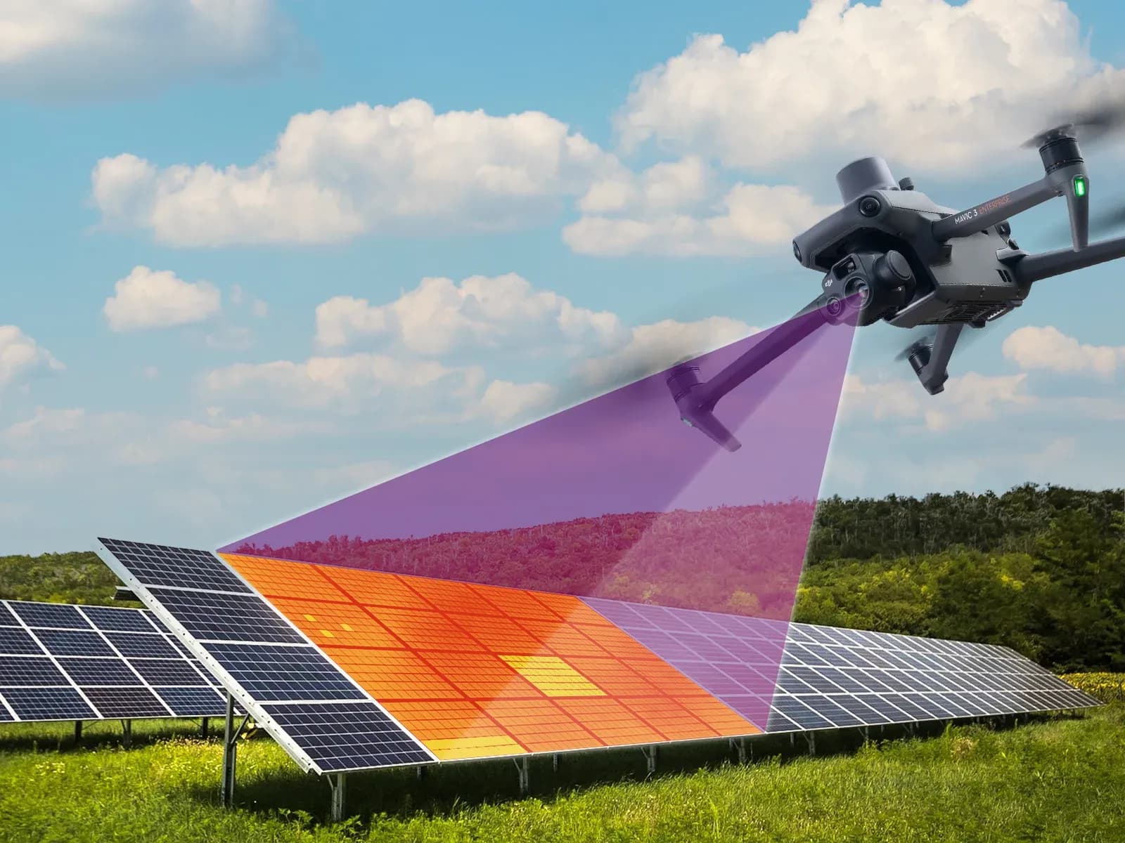
IEC 62446-3 addresses outdoor thermographic inspection of operating photovoltaic systems. Its scope concerns how thermographic inspection should be prepared, performed, interpreted, and reported under field conditions. It deals with the inspection process rather than with the commercial features of a particular drone, camera, or software package.
For an inspector, the value of the document is that it gives structure to a measurement method that is highly dependent on environmental and operating conditions. Thermal images can change with irradiance, wind, cloud cover, module temperature, reflections, viewing geometry, and the electrical state of the array. A disciplined procedure is therefore necessary if images from different parts of the site are expected to support comparable findings.
The document also addresses equipment, environmental conditions, inspection procedure, personnel competence, and reporting. These subjects are connected. A suitable infrared camera does not compensate for unsuitable weather, and good weather does not compensate for an acquisition method that cannot resolve the feature being inspected.
IEC 62446-3 should therefore be applied as an inspection framework. It helps an inspector define what information must be captured and under what conditions, but it does not turn every temperature difference into a confirmed electrical defect.

Inspection Conditions for PV Thermography
Outdoor PV thermography depends on the plant being in a meaningful operating state during the inspection. Irradiance affects the electrical loading of the modules and therefore influences whether temperature differences associated with abnormal behavior become visible. A thermal pattern recorded under weak or rapidly changing solar conditions may not be comparable with one recorded under stable, higher irradiance.
Wind matters because convective cooling can reduce or distort surface temperature differences. Cloud movement can change irradiance across the array during a flight, creating variations between rows or image sequences that are caused by changing conditions rather than by the modules themselves. An inspector should therefore record the conditions present during acquisition instead of treating the thermal image as context-free evidence.
Module temperature is also relevant to interpretation. The absolute surface temperature of one module should not be evaluated without reference to surrounding modules, electrical loading, environmental conditions, and the inspection objective. IEC 62446-3 does not impose one universal temperature range that determines whether every PV module in every plant is acceptable.
Reflections are another source of error. Glass and other module surfaces can reflect thermal radiation from the sky, nearby objects, the aircraft, or the inspector's surroundings. A thermal image can contain apparent hot or cold regions that come from reflection rather than from the module itself.
Viewing angle affects both reflections and the apparent geometry of the target. The flight or capture plan should avoid angles that make interpretation unreliable and should maintain sufficient consistency across the inspected area. Measurement discipline means recording these influences rather than assuming that every pixel represents the true temperature of the underlying cell.
Thermography Procedure and Competence
A useful thermographic inspection begins with a defined acquisition plan. The inspector should know which arrays, rows, modules, or plant areas are included, what image resolution is required, how the aircraft or camera will move through the site, and which conditions would make the inspection unsuitable. The plan should also account for obstacles, inaccessible zones, module orientation, and the need to associate thermal findings with physical locations.
Target resolution is important because small cell-level features cannot be interpreted if the image acquisition does not resolve them. Flight height, camera resolution, lens characteristics, angle, and motion all influence how much detail is available. Software cannot reconstruct a reliable cell-level anomaly from data that were never captured with adequate spatial resolution.
The operator also needs enough competence to recognize when acquisition conditions make the data unreliable. That includes understanding reflections, thermal contrast, focus, viewing geometry, environmental effects, and the limitations of temperature measurements. Competence is part of the inspection process because errors made during capture can look like equipment defects later.
Where drones are used, flight operation and thermographic inspection should be coordinated rather than treated as unrelated tasks. A flight path designed only for area coverage may not provide the geometry or resolution needed for meaningful thermal interpretation. The inspection objective should determine the image acquisition method, not the other way around.
Personnel evaluating the results should also distinguish between thermal observation and electrical diagnosis. Identifying an unusual temperature pattern is different from proving why that pattern exists.
Thermal Abnormality Classification and Interpretation
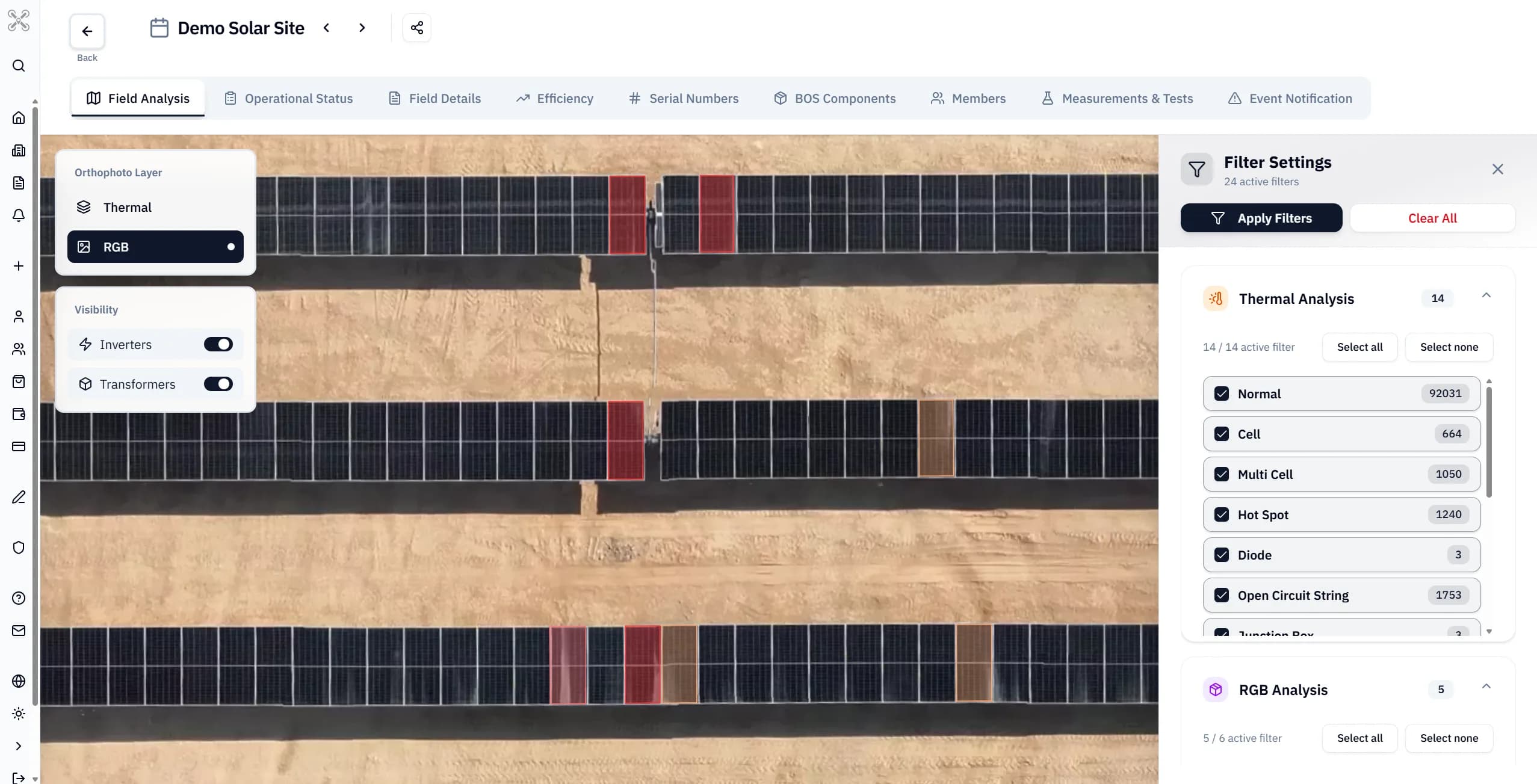
Thermal inspection can reveal localized temperature differences associated with cell areas, interconnections, bypass-diode behavior, strings, connectors, or other electrical conditions. In practical software workflows, these observations may be organized under product labels such as hotspot, cell anomaly, diode-related pattern, or open-circuit string. Those labels should not be confused with formal IEC definitions unless the standard explicitly defines the same category and criteria.
A thermal pattern by itself does not prove root cause. A warm cell area may result from several different electrical or physical conditions, and an apparently cool or warm string may reflect operating state, shading, measurement geometry, disconnection, or another system condition. The inspector should describe the observed pattern before assigning a cause.
Comparison with neighboring modules can be useful when the modules have similar orientation, electrical configuration, irradiance, and operating conditions. Even then, the comparison should be treated as supporting evidence rather than as an automatic defect decision. Visible imagery, plant monitoring data, circuit information, and electrical testing may be needed to confirm what the thermographic observation means.
This distinction is important for maintenance decisions. A report can legitimately identify a localized thermal abnormality that requires follow-up. It should not state that a component has failed unless sufficient evidence supports that conclusion.
Thermography is therefore a screening and inspection method, not a complete fault-diagnosis system. The strongest reports preserve that boundary clearly.
Report Requirements
A thermographic report should make it possible for another qualified person to understand what was inspected and under what conditions. That includes who performed the inspection, when it was performed, the plant or area covered, the equipment used, and the environmental and operating conditions that were relevant to interpretation.
The report should identify each significant finding in a way that connects it to a physical location. Thermal and corresponding visible images can be included where they support identification or interpretation. The record should make clear which module, row, string, block, or equipment item was observed and what thermal pattern was detected.
Inspection conditions should be recorded with enough detail to explain the quality and comparability of the measurements. Irradiance, wind, cloud conditions, module temperature, flight or camera geometry, and other relevant parameters should be documented where they affect the result. Areas that could not be inspected reliably should be listed as limitations rather than silently treated as satisfactory.
The report should also separate observation from conclusion. "Localized elevated temperature relative to adjacent cells" is an observation. "Failed bypass diode" is a diagnosis that requires additional evidence unless the available inspection data support it directly.
Good records also allow repeat inspections to be compared more carefully. Without conditions, location, method, and image context, a thermal record has limited long-term value.
What the Standard Does Not Do
IEC 62446-3 is not a software algorithm. It does not prescribe how a commercial application must detect, classify, or score anomalies, and it does not make a software output compliant merely because the software uses thermal images. The inspection procedure and evidence remain central.
The document also does not impose one universal temperature threshold or temperature range for every PV plant. Module technology, operating conditions, irradiance, wind, geometry, and the type of abnormality all affect interpretation. A single fixed number applied across unrelated sites would ignore the measurement context that thermography requires.
The standard does not mean that every thermal abnormality is a confirmed fault. Nor does it replace electrical tests, visual inspection, monitoring data, or engineering judgment where those are needed to determine cause or severity. A thermal image can indicate where attention is warranted without proving the final diagnosis.
It also does not, by itself, issue a conformity decision for an entire plant. Compliance or acceptance may require additional inspection and test activities outside thermography.
Applying It in an Inspection Workflow
In practice, the inspector can use IEC 62446-3 to structure the workflow from planning through reporting. The process begins by defining the inspection scope, confirming suitable environmental and operating conditions, selecting equipment, and determining the image resolution and geometry needed for the intended findings.
During acquisition, conditions should be checked continuously. If cloud movement, wind, reflections, loss of focus, or unsuitable viewing angle compromise the images, those areas should be repeated or marked as limited. Completing a flight path is not more important than obtaining interpretable data.
After acquisition, thermal observations should be reviewed alongside visible images, plant layout, electrical topology, and available monitoring information. Findings can then be grouped by location and observation type without overstating the cause. Where further verification is required, the report should state that explicitly.
The final record should preserve enough context for maintenance personnel to locate the affected equipment and decide what follow-up test or inspection is appropriate. That may involve electrical measurements, visual inspection, connector checks, or other plant-specific procedures.
Used this way, the standard supports consistency and traceability. It does not replace technical judgment, and it does not turn thermography into a stand-alone proof of plant condition.