Solar Panel Thermal Inspection
How thermal inspection finds faulty solar panels at module level, what IEC 62446-3 requires and how drone data becomes a traceable report.
What Thermal Inspection of Solar Panels Is
Thermal inspection of solar panels uses infrared imaging to record temperature patterns across modules and related electrical components while the PV system is operating. The purpose is to identify areas that behave differently from comparable equipment and may require closer investigation. It is an inspection method based on thermal evidence, not a complete electrical diagnosis.
PV modules can develop temperature differences for several reasons. Cell damage, shading, bypass-diode behavior, connection resistance, contamination, circuit conditions, and environmental effects can all influence the image. A thermal abnormality therefore identifies a location of interest rather than proving what has failed.
The method is especially useful on large arrays because many modules can be compared within the same inspection. Instead of beginning with electrical measurements on every module, the field team can first locate candidates and then decide where direct verification is justified.
IEC 62446-3 addresses outdoor thermographic inspection of operating PV systems. Its scope includes inspection equipment, environmental conditions, procedures, personnel competence, and reporting. It does not define a software algorithm and does not impose one universal module-temperature range for every PV plant.
How Thermal Inspection Works on an Operating Array
PV modules convert incident solar energy into electricity while part of that energy is released as heat. Their operating temperature depends on irradiance, electrical loading, module construction, ambient temperature, wind, mounting arrangement, and other conditions. A component that operates differently from its neighbors may therefore produce a different surface-temperature pattern.
The inspection usually relies on comparison. Modules with similar orientation, technology, electrical configuration, irradiance, and operating state provide a useful reference for one another. If one module or cell area is significantly different from nearby comparable equipment, the observation can be marked for review.
The array must be operating under conditions that allow useful thermal contrast to develop. Weak or rapidly changing irradiance, strong wind, cloud movement, or an unusual electrical state can reduce the value of the comparison. This is why thermal inspection should not be treated as simply pointing a camera at the array.
A thermal inspection can also include electrical equipment beyond the module surface where the inspection scope requires it. Connectors, terminals, fuse holders, junction boxes, or other current-carrying components may exhibit localized heating that deserves follow-up.
The operating state matters throughout the survey. A disconnected string, shaded row, or curtailed inverter input may produce a thermal appearance that differs from neighboring equipment without necessarily indicating a component defect.
What a Thermal Image Shows and What It Does Not
A thermal image can show localized hot cells, larger warm regions, cooler modules, unusual string-level patterns, or heating around connections. These observations can be useful because they show where temperature behavior differs under the conditions present at the time of inspection.
A warm cell does not automatically mean that the cell itself is permanently defective. Shading, interconnection behavior, mismatch, physical damage, or other electrical conditions can produce similar patterns. The thermogram should therefore describe the observation before any root cause is assigned.
Bypass-diode behavior may also create recognizable module-level patterns under some operating states. Those patterns can justify inspection of the module and its electrical behavior, but the image alone should not be treated as proof that a diode has failed.
Connection heating follows the same principle. A connector or terminal operating warmer than comparable equipment can indicate increased resistance or another abnormal condition, but physical inspection and direct electrical verification may still be required.
Soiling can influence the thermal image as well. Dust, bird contamination, vegetation, or other material may change the light reaching part of a module and alter its electrical behavior. Visible imagery is often useful for distinguishing external surface conditions from other causes.
Thermal inspection therefore identifies candidates and patterns. It does not prove insulation resistance, polarity, current capability, IV behavior, or the overall safety of the plant.
Thermal Inspection with a Drone
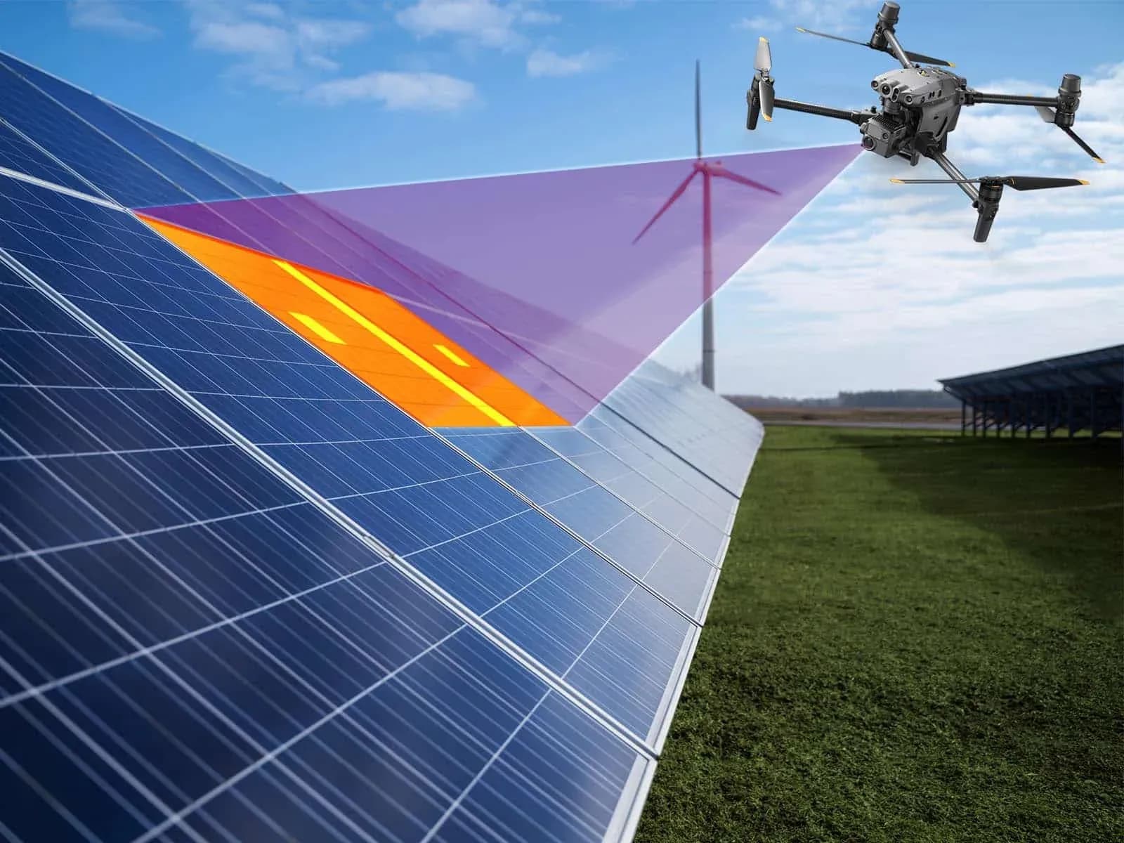
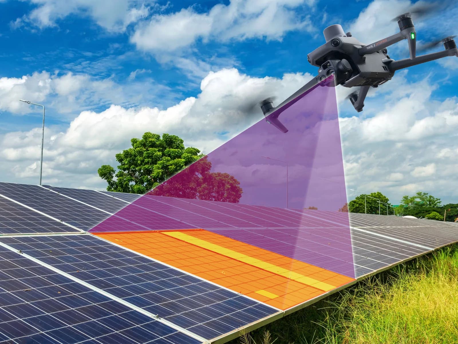
Aerial thermography allows the inspection team to collect thermal imagery across large PV fields without walking every row during the initial screening stage. A drone can follow a planned route above the array and record thermal and visible imagery together with location information.
The flight should be designed around the feature that needs to be resolved. Module-level screening can use a different altitude and image density from cell-level review. Flight height, thermal resolution, lens, speed, viewing angle, and target size all influence whether the captured data is suitable for interpretation.
Visible imagery can provide useful context alongside the thermal record. Broken glass, contamination, vegetation, shading, displaced components, or other physical conditions may explain or help interpret an unusual thermal pattern.
Aerial inspection can reduce unnecessary field movement on large sites, but the practical benefit depends on terrain, airspace, weather, site access, required resolution, and the amount of ground verification required afterward. It should not be presented as universally faster or cheaper in every plant.
The drone is a data-acquisition platform. It does not remove the need for competent interpretation, electrical testing, or direct access to equipment when the finding requires confirmation.
Acquisition Conditions and Comparability
Irradiance is one of the main variables affecting PV thermography. It influences current production and the thermal contrast associated with many operating abnormalities. If irradiance changes substantially during a survey, two images collected at different times may not represent comparable electrical loading.
Wind affects module temperature through convective cooling. Strong or variable wind can reduce temperature differences that might otherwise be visible. A finding that appears clearly under calm conditions may become less obvious under stronger airflow.
Cloud movement can produce rapid changes in solar input. A module imaged shortly after a cloud passes may still be heating or cooling when the image is captured. This can create differences between rows that come from timing rather than equipment condition.
Module temperature should also be recorded where relevant, but it should not be converted into a universal pass/fail threshold. IEC 62446-3 does not prescribe one acceptable temperature range for every module technology, site, or operating state.
Viewing angle introduces another source of uncertainty because PV glass reflects infrared radiation. The sky, terrain, vegetation, structures, or the aircraft can produce apparent hot or cool regions. Reflections should therefore be considered before a thermal pattern is classified as an equipment finding.
Repeat inspection is most useful when these conditions are documented consistently. A similar flight path alone does not make two surveys directly comparable if the thermal acquisition conditions differ.
When Electrical Verification Is Needed
Electrical verification is needed when the maintenance decision depends on a property that thermal imagery cannot establish directly. Current and voltage measurements can help evaluate string behavior, while IV-curve testing can provide a broader view of electrical performance over a range of operating points.
Insulation resistance testing may be required where moisture ingress, damaged cables, broken modules, or another condition raises questions about electrical isolation. A module can have acceptable thermal appearance while still having an insulation problem.
Continuity testing answers a different question by checking whether designated protective conductors or bonding paths remain electrically connected. Polarity testing may be required where conductor orientation or wiring changes are uncertain.
A suspected connector problem can require both physical inspection and electrical measurement. The thermal image identifies that the connector is operating differently; it does not measure contact resistance or prove why the temperature is elevated.
The correct test should follow the suspected mechanism. Running unrelated measurements without a defined question can add data without improving the diagnosis.
Thermal inspection and electrical testing are therefore complementary. The thermal survey narrows the search, while direct measurement confirms the electrical property needed for the maintenance decision.
Where Thermal Inspection Fits in a Maintenance Program
Thermal inspection is one part of a wider O&M process that can include monitoring, visual inspection, electrical testing, functional checks, cleaning, vegetation management, corrective work, and maintenance records. Its role is strongest where temperature patterns can help locate operating abnormalities.
Scheduled thermography can create a repeatable condition record, while event-driven surveys can investigate specific areas after production deviations, storms, maintenance activity, or other events. The inspection scope should always be tied to the question being investigated.
Thermal findings should be linked to physical assets and followed through to verification and closure. The original image, module or string location, environmental conditions, electrical follow-up, corrective action, and later inspection can all form part of the same record.
One thermal inspection is not continuous monitoring. Intermittent conditions may not appear during the survey, and new faults can develop afterward. Monitoring and later field checks remain relevant between inspections.
Software can help organize imagery, map findings, compare inspections, and maintain records, but it does not replace electrical testing or qualified technical judgment.