
PV Combiner Box Test
PV combiner box inspection and testing assess the specified string connections, protective devices and electrical measurements before or during operation.
What Is the PV Combiner Box Test?
A PV combiner box collects the outputs of multiple PV strings and combines them into one or more DC circuits before power is passed toward the inverter or another downstream DC stage. Depending on the plant design, the enclosure may contain string fuses, disconnecting devices, surge protection devices, monitoring components, terminals, busbars, and associated protective conductors.
Inspection and testing assess the specified string connections, protective devices, identification, polarity, physical condition, and electrical measurements before or during operation. Measurements and observed conditions are compared with the plant design, equipment documentation, expected operating state, and the test procedure being used. Findings can identify conditions requiring correction; they do not automatically optimize plant output or prove that the complete PV installation is safe.
De-energized inspection and live electrical measurement should be treated as separate activities. Some items can be examined only after an appropriate isolation procedure, while string voltage or current measurements may require the circuit to be operating. The work plan should define which condition is required for each check.
DC connectors or unsuitable fuse holders should not be opened under load. Interrupting DC current through equipment that is not designed for load breaking can create hazardous arcing and equipment damage.
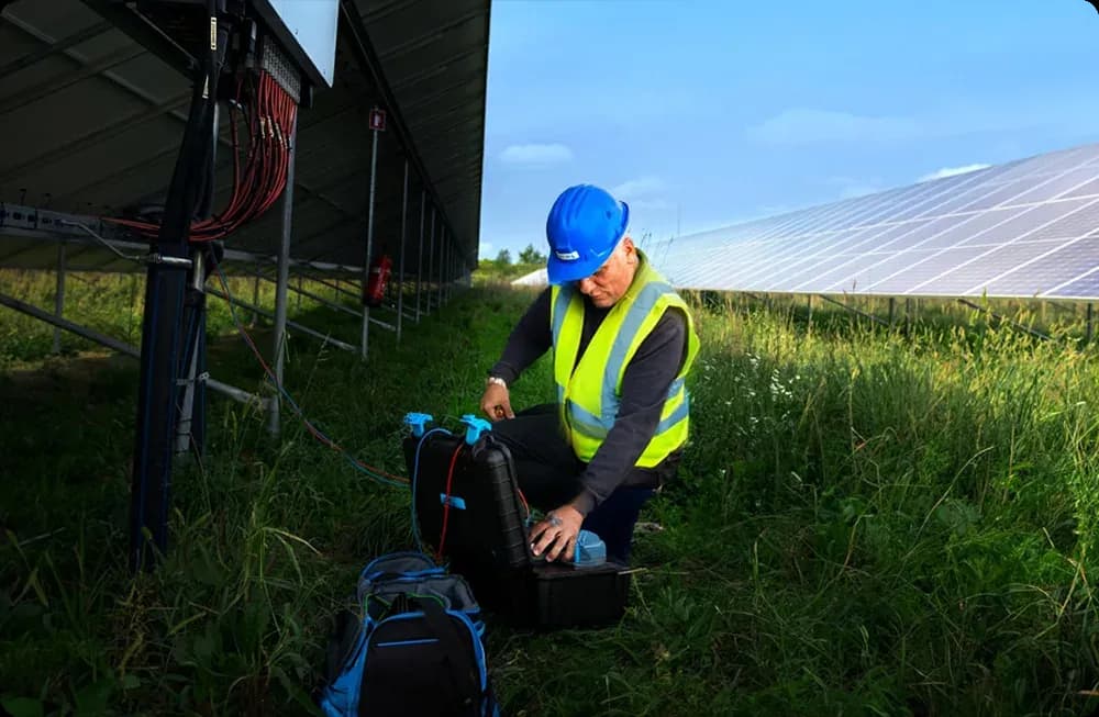
Why Is the Combiner Box Tested?
The first objective is to confirm that strings are connected in accordance with the intended circuit arrangement. Incorrect labeling, reversed polarity, missing strings, crossed connections, loose conductors, or wiring that differs from the drawings can make troubleshooting difficult and may create unsafe or abnormal operating conditions.
The second objective is to inspect protective and switching components that form part of the DC system. Fuses, disconnectors, surge protection devices, terminals, protective conductors, and other components should be checked according to their function and the manufacturer's information. A component that is physically present should not automatically be assumed to be correctly rated, correctly connected, or functional.
Combiner-box measurements can also support investigation of production differences. If one string carries materially different current from comparable strings under similar conditions, the result may justify further inspection of that string, its modules, connectors, cabling, shading conditions, or measurement channel. The combiner-box test narrows the investigation; it does not establish the cause from a single current value.
The inspection also supports DC safety by identifying visible or measurable conditions that require correction. It remains one part of the plant's electrical verification rather than a complete safety assessment.
Preparation and Safety Before Testing
The team should start with current drawings, string schedules, equipment information, labels, and the inspection scope. Knowing which strings should terminate in the box, their expected polarity, the protective-device arrangement, and the downstream circuit makes it possible to compare the physical installation with the intended design.
Before opening or working inside the enclosure, personnel should assess the electrical state of the equipment. PV strings can remain energized whenever sufficient light is available, and isolating the inverter side does not necessarily remove voltage from incoming string circuits. Safe access therefore depends on the actual circuit arrangement rather than on the position of a single switch.
De-energized activities should follow the applicable isolation and verification procedure for the site. Where measurements must be made on operating circuits, the equipment, test leads, probes, protective equipment, and working method should be suitable for the DC voltage and prospective conditions present.
No connection should be disturbed merely to make an inspection easier. In particular, connectors, terminals, and fuse carriers that are not intended for load breaking should not be opened while carrying current. If the inspection requires disconnection, the circuit should first be placed in the required safe state using the approved procedure.
Measurements Typically Taken
String current is commonly measured where the combiner design provides safe access or monitoring points. Current values from electrically comparable strings can be reviewed together when irradiance, orientation, shading, module configuration, and operating conditions are sufficiently similar. A difference can indicate a condition that deserves investigation, but current alone does not identify whether the cause is a module problem, shading, connection resistance, fuse condition, measurement error, or another factor.
String or circuit voltage may also be measured and compared with the expected configuration. Voltage measurements can help reveal reversed polarity, open circuits, unexpected series configuration, or other wiring differences. Interpretation should account for array configuration, module temperature, irradiance, inverter operating state, and whether the measurement is open-circuit or made under operation.
Polarity should be verified where required by the inspection procedure. Incorrect polarity can damage equipment or prevent normal operation, so the test should be made using an instrument and method appropriate to the DC system rather than inferred only from cable color or labeling.
Insulation testing may be part of a broader PV electrical inspection when appropriate for the circuit and equipment state. It should not be performed casually through connected electronics or surge protection devices without considering the test voltage and manufacturer requirements, because inappropriate insulation testing can damage connected equipment or produce misleading results.
What a Good Combiner Box Report Contains
A useful report identifies the exact combiner box, the circuits examined, and the strings or outputs associated with each measurement. String labels should correspond to field identifiers or drawings closely enough that another technician can locate the same circuit without reconstructing the inspection from memory.
The report should state what was inspected while de-energized and what was measured while the system was operating. Relevant operating conditions should be recorded when they affect interpretation, particularly for comparative current measurements. The measuring instrument, measurement function, and applicable test settings should also be documented.
Observed component condition should be separated from measured values. A damaged fuse holder, discolored terminal, missing label, or disconnected monitoring lead is a visual finding; current, voltage, or insulation resistance is a measured result. Keeping the two categories distinct makes the report easier to review and reduces the risk of turning an observation into an unsupported diagnosis.
Findings that require confirmation should be marked accordingly. A current imbalance can justify follow-up testing, but the report should not call a module defective unless evidence supports that conclusion.
Common Findings in PV Combiner Boxes
Field teams may find incorrect or missing string labels, reversed polarity, open string circuits, blown fuses, unsuitable replacement fuses, loose terminations, damaged insulation, corrosion, contamination, water ingress, damaged cable glands, degraded surge protection devices, or disconnected monitoring equipment. Evidence of heating or discoloration can indicate a connection that deserves further investigation.
Unequal current between otherwise comparable strings is another common reason for follow-up. The cause may be outside the combiner box, including shading, soiling, module damage, connector problems, string configuration differences, or conditions elsewhere in the DC circuit. The combiner measurement identifies where behavior differs; it should not be used to assign root cause without further evidence.
Some apparent findings are measurement problems rather than equipment defects. Incorrect clamp orientation, unsuitable meter range, poor probe contact, unstable irradiance, or comparing strings with different orientations can create misleading results. Unexpected values should therefore be checked against the circuit arrangement and measurement conditions before corrective work is specified.
A good inspection process records inaccessible or untested circuits as limitations rather than silently treating them as satisfactory.
Limits of the Combiner Box Test
A combiner-box inspection covers the equipment and circuits included in its defined scope. It does not prove inverter efficiency, maximize power production, verify the complete mechanical condition of the array, or establish the safety of the entire plant. Other inspections and tests may be needed for modules, connectors, cabling, insulation, earthing, inverter operation, protective devices, and structural components.
Electrical measurements also describe the plant only under the conditions present when they were taken. A string that appears normal during one measurement can later develop an intermittent connection, shading condition, insulation problem, or component failure. One inspection is therefore not equivalent to continuous monitoring.
Thermal imaging can support investigation of heated terminals or other temperature anomalies, but a thermal image by itself does not confirm the cause of a fault. Electrical measurements, visual evidence, equipment condition, operating data, and follow-up testing may all be required before a defect is classified.
IEC 62446-3 concerns outdoor thermographic inspection of operating PV systems. Its scope includes equipment, environmental conditions, inspection procedures, personnel competence, and reporting, and it does not impose one universal temperature range for every PV plant. It should not be presented as a software algorithm or as a substitute for the electrical procedures used to test a combiner box.