
Field Design with Drone Use in Solar Energy
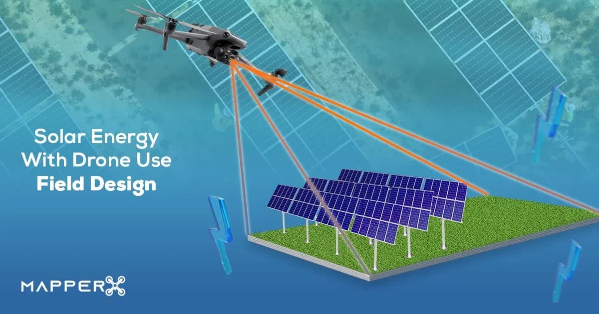
Field design with drone use in solar energy: pre-construction site assessment provides inputs for solar design, from ground analysis to aerial imaging.
Drone Data in the Design Stage
Drone surveys can provide current spatial information about a proposed solar site before detailed layout work begins. Aerial imagery can show field boundaries, access routes, existing structures, vegetation, drainage features, terrain changes, and other physical conditions that may affect how the site is used.
The main design value is context. Instead of relying only on older satellite imagery or incomplete site drawings, the project team can review a recent representation of the land and relate proposed equipment to visible site features. This can help identify areas that deserve closer ground survey or engineering review.
Drone data can also support preliminary measurement of distances, areas, and relative elevations when the survey has been planned and controlled for that purpose. The reliability of those measurements depends on positioning quality, image geometry, ground control, processing method, and the accuracy required by the design task.
A drone map should not automatically be treated as a substitute for cadastral, geotechnical, structural, or survey-grade information. Its role depends on the precision of the acquisition and on the decision being made.
The design team should therefore define the required confidence before the flight. Data suitable for early layout comparison may not be suitable for final foundation coordinates or other engineering decisions that require tighter control.
Ground Analysis and Terrain
Terrain influences row layout, structure design, drainage, construction access, cable routing, and later maintenance. Drone-derived surface models can help show changes in slope and elevation across the site, allowing designers to identify areas that may need more detailed survey or engineering attention.
Slope is not only a question of whether modules can physically be installed. It can affect grading, foundation exposure, access roads, erosion, vehicle movement, row-to-row shading, and the relationship between tracker or fixed-tilt structures and the ground.
Drainage is equally important. Existing channels, low points, water paths, and areas that appear prone to ponding can influence equipment placement and road design. Aerial imagery can document visible drainage features, but hydrological conclusions require the appropriate engineering analysis and site information.
Access roads and working areas should be considered early because construction and maintenance need physical routes to equipment. A layout that maximizes module density while leaving poor access can create recurring operational difficulty after commissioning.
Trees, buildings, poles, terrain, and other objects can also be recorded as potential shading sources. Aerial geometry can support shading analysis, but one image at one time of day is not a complete annual shading assessment.
Ground conditions beneath the surface remain outside normal image-based mapping. Soil strength, geotechnical properties, buried utilities, and foundation suitability require separate investigation.
Aerial Imaging and 3D Modeling
Overlapping drone photographs can be processed into orthophotos, point clouds, elevation models, and three-dimensional representations of the site. These products can help designers review relationships between terrain, existing structures, roads, proposed module rows, and other site elements.
A 3D model is useful because flat imagery can hide changes in elevation that influence layout or construction. Designers can inspect slopes, compare alternative positions, and identify places where ground geometry may create conflicts with access or structure height.
Model quality depends on the original imagery. Flight height, camera characteristics, image overlap, lighting, motion, ground control, and positioning all affect the reconstruction. Repetitive textures or areas with poor visual features can reduce reliability.
The model should therefore be checked before it becomes a design reference. Distorted surfaces, missing areas, duplicated features, or incorrect elevation can appear plausible on screen while still being unsuitable for engineering decisions.
Ground control points or other surveyed references can improve positional control when correctly measured and distributed. They do not remove every possible source of error, and their use should match the accuracy required by the project.
Three-dimensional reconstruction is best treated as a design input that improves spatial understanding. Final engineering decisions still need the measurements and calculations appropriate to their technical discipline.
Layout and Spacing Decisions
Drone-derived site information can make preliminary layout decisions easier by showing where module rows, roads, inverter areas, drainage corridors, fences, and other site elements would interact. Designers can compare alternatives using the actual terrain rather than a generic flat field.
Row spacing is influenced by shading, module geometry, mounting system, maintenance access, terrain, and project objectives. Aerial data can help represent these physical constraints, but it does not determine the correct spacing automatically. Solar geometry and the electrical and structural design still need separate calculation.
Terrain information can also help identify areas where rows may require different elevations, grading, or alignment. On irregular sites, a uniform layout applied without reference to the ground can create access or construction problems that become obvious only after work begins.
Existing roads, vegetation, structures, waterways, and boundary features can be incorporated into layout review. This may reduce conflicts discovered later, although the benefit depends on the completeness and accuracy of the survey.
Design teams should also consider later inspection and maintenance access. Leaving practical routes for vehicles, cleaning equipment, vegetation control, replacement work, and emergency access may be more important than maximizing the number of modules in every available space.
The drone assists with spatial decisions. It does not choose the electrical string design, cable rating, protection arrangement, foundation strength, or other engineering parameters that require dedicated calculation.
Aerial Monitoring During Construction
Drone surveys can also document how the site changes during construction. Repeated flights can show progress in road formation, structure installation, module placement, equipment areas, trench routes, and other visible parts of the project.
This record can help design and construction teams compare the installed layout with previous site information. A visible difference may identify an area that deserves review before later work makes correction more difficult.
Repeat routes can improve comparability when altitude, geometry, and map references are kept consistent. Even then, changes in lighting, vegetation, temporary equipment, and ground condition can affect what is visible between flights.
Aerial imagery may also document construction access or temporary conditions that are useful during coordination. It does not prove that installed electrical connections, torque values, foundations, structural members, or buried systems meet their technical requirements.
Construction monitoring therefore works best as a visual and spatial record. Detailed acceptance still requires the relevant engineering inspection, test, survey, and documentation for each discipline.
A flight should also respect site safety and aviation constraints. Active cranes, workers, vehicles, temporary structures, dust, and changing access routes can all affect whether and how the aircraft can operate.
Reporting for Design Reviews
A useful design report should state what data was collected, when it was collected, and how it was processed. Flight height, camera information, coordinate system, ground control where used, and known limitations help reviewers understand what decisions the dataset can reasonably support.
Maps should identify significant features clearly enough that another reviewer can locate them. Terrain changes, roads, obstacles, shading objects, drainage features, boundaries, and areas of uncertain reconstruction can be marked without converting every visible object into an engineering conclusion.
Where measurements are derived from the drone model, the report should distinguish approximate planning information from values intended for higher-precision engineering use. That distinction prevents a convenient visual model from being used outside the accuracy for which it was collected.
Design review also benefits from preserving alternative layouts and the reasons for changing them. If a row is moved because of terrain, access, drainage, or an obstacle, the spatial evidence can remain part of the design record.
The report should identify areas requiring ground verification. Dense vegetation, poor imagery, water, reflective surfaces, or obstructed zones may reduce confidence and justify additional survey.
Aerial data becomes more useful when its limitations are visible in the report rather than hidden behind a polished map.
Limits
Drone maps and three-dimensional models contain measurement uncertainty. Positioning error, camera calibration, flight geometry, ground control, processing choices, terrain, and image quality can all affect the final representation. A detailed-looking model should not be assumed to have survey-grade accuracy unless the acquisition and validation support that claim.
Aerial imagery also cannot reveal every condition needed for design. Soil properties, buried infrastructure, internal structural condition, electrical characteristics, and many material properties remain outside normal visual mapping.
Structural decisions require their own engineering verification. Foundation design, wind loading, structural capacity, mounting calculations, and similar questions should not be decided from the appearance of a 3D model alone.
Electrical design has the same boundary. Drone data can show where equipment might fit, but it does not determine cable sizing, string configuration, protection settings, earthing, voltage drop, or equipment ratings.
Thermal inspection may later be combined with mapped site data during operation. IEC 62446-3 concerns outdoor thermographic inspection of operating PV systems, including equipment, environmental conditions, procedure, personnel competence, and reporting. It does not provide design approval for the plant or turn mapping software into an engineering calculation tool.
Drone data therefore assists design review by improving spatial awareness. Engineering decisions still require the appropriate survey, calculation, test, and professional verification for the specific question.