
PV Grounding Continuity Test
PV grounding continuity test checks the electrical connection between designated exposed conductive parts and the protective conductor system.
Grounding Continuity Test
Protective bonding continuity testing checks whether designated exposed conductive parts are electrically connected to the protective conductor system through a sufficiently continuous path. In a PV installation, this can include module frames, mounting structures, metallic enclosures, equipment housings, bonding conductors, and other conductive parts identified by the system design. The test supports electrical safety verification; it does not by itself guarantee that the installation is safe or improve the conversion efficiency of PV modules.
The purpose is to verify the continuity of the intended protective path rather than to prove that every grounding-related function is correct. A low-resistance connection between two tested points can confirm that the specific path being measured is continuous, but it does not demonstrate correct fault protection throughout the entire plant. Earthing arrangement, protective-device operation, conductor sizing, connections, insulation condition, and other aspects may need separate inspection or testing.
For field teams, continuity testing is therefore best treated as one defined part of a broader electrical verification process. The test should answer a specific question: is the designated protective conductor path between these points present and electrically continuous?
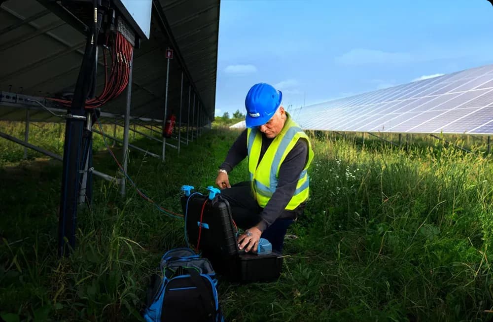
What Is a Grounding Continuity Test?
A grounding continuity test measures resistance along a protective conductor or bonding path between selected conductive points. The field instrument applies a suitable test current and measures the resulting resistance, allowing the technician to identify open circuits, weak connections, or unexpectedly high resistance along the path being checked. The measured value is interpreted against the installation design, test method, conductor length, conductor material, connections, and applicable acceptance criteria.
This test should not be confused with an earth electrode resistance test. Protective bonding continuity concerns the electrical continuity between exposed conductive parts and the protective conductor network. Earth electrode testing evaluates the resistance associated with an earthing electrode system and its connection to the surrounding earth; the methods answer different questions and should not be treated as interchangeable.
Test-lead resistance also matters when low resistance values are being measured. Depending on the instrument and method, the technician may need to null, compensate for, or separately record the resistance of the leads before assessing the installation. Ignoring lead resistance can distort the result, particularly when the expected conductor resistance is itself small.
Testing should be carried out by competent personnel using procedures appropriate to the installation state. Isolation, verification of absence of voltage where required, control of stored energy, and confirmation that the selected test points can be accessed safely should be addressed before connecting test equipment.
Why Is the Grounding Continuity Test Performed?
The test is used to find missing, damaged, disconnected, corroded, or excessively resistive protective connections. A conductor may appear physically present while a loose fastener, damaged termination, corrosion layer, unsuitable joint, or broken bonding link prevents it from providing the intended low-resistance path. Direct measurement gives the field team evidence that visual inspection alone may not provide.
A continuous protective path helps limit hazardous potential differences between exposed conductive parts when the electrical protection concept relies on bonding. The exact arrangement depends on the system design, including how modules, structures, inverter equipment, combiner boxes, distribution equipment, and earthing conductors are interconnected.
The existence of some conductive path toward earth is not by itself proof of effective electric-shock protection. A path can exist while still having excessive resistance, incorrect routing, inadequate connections, or protection devices that do not operate as intended. The result therefore has to be interpreted within the complete protection scheme rather than as a stand-alone safety certificate.
Continuity testing can also be useful after maintenance, structural work, module replacement, cable work, or other interventions that may disturb bonding connections. In those cases, the test can confirm whether the affected protective path remains intact after the work is completed.
Why Is the Grounding Continuity Test Important?
PV plants contain large numbers of repeated mechanical and electrical connections distributed across outdoor environments. Moisture, temperature cycling, contamination, mechanical movement, corrosion, maintenance activity, and accidental damage can all affect a protective connection over time. A continuity test provides a direct electrical check of the selected bonding path rather than relying only on its visible condition.
The test is particularly important where several conductive components depend on a chain of bonds to reach the main protective conductor. A failure at one point can interrupt continuity for equipment farther along that path, even if those downstream components appear correctly connected. Testing at suitable locations can help identify where continuity is lost.
Results can also support maintenance decisions by showing which paths require physical inspection or repair. An unexpected resistance value should normally lead to investigation of the relevant connections, conductors, terminals, bonding jumpers, or contact surfaces rather than an assumption about the exact cause.
Continuity results should be preserved with enough context to be compared later. A recorded resistance without the test points, lead arrangement, instrument, and acceptance basis has limited diagnostic value.
How the Test Is Carried Out
The field team first identifies the protective paths that are intended to be tested from drawings, labels, equipment documentation, or the installation design. Suitable test points are then selected so that the measured path corresponds to the conductor route being assessed. Before testing, personnel should determine whether the circuit or equipment needs to be isolated and confirm that connecting the instrument will not expose the operator or equipment to an unsafe condition.
The test instrument and leads are checked before measurements begin. Where required, lead resistance is compensated or documented so that it does not become part of the installation result. The probes or clips should make reliable contact with the conductive surface; paint, oxidation, dirt, or poor probe pressure can produce misleading readings.
Measurements are then taken across the defined bonding paths. If an unexpectedly high value is recorded, the technician can divide the path into shorter sections to locate the part contributing the additional resistance. This approach is usually more useful than repeating the same end-to-end measurement without examining intermediate connections.
The final result should be judged against the acceptance basis selected for that installation and test method. A resistance number should not be declared acceptable merely because it appears small in isolation.
Acceptance Criteria and Records
A useful test record identifies exactly which protective paths were examined and the measured value for each path. It should also record the instrument used, relevant instrument identification or calibration information where maintained by the inspection process, lead compensation method, test conditions, and the criterion used to classify the result.
The acceptance criterion should come from the applicable design, commissioning specification, equipment information, inspection procedure, or other documented basis used for the installation. A single arbitrary resistance threshold should not be applied to every PV plant without considering conductor length, material, cross-section, connection arrangement, and the method being used.
Records should distinguish measured facts from interpretation. For example, "0.18 Ω measured between enclosure A and protective-conductor bar B" is a measurement; "bonding conductor connection requires verification" is a follow-up finding. Keeping these separate makes subsequent review clearer.
A continuity result alone is not a complete conformity assessment. Additional visual inspection and electrical tests may be needed to evaluate insulation, polarity, protective-device operation, earthing arrangements, or other parts of the installation.
Common Findings and Limits of the Test
Typical findings include disconnected bonding jumpers, loose terminals, corroded contact points, damaged conductors, missing connections after component replacement, and resistance that is higher than expected for the tested path. Measurement problems can also occur when probes contact coated metal, oxidized surfaces, or unsuitable test points, so an abnormal reading should be verified before a repair conclusion is made.
A satisfactory continuity result only applies to the path and condition actually tested. It does not prove correct earth electrode resistance, insulation integrity, protective-device performance, conductor sizing, or overall plant safety. It also does not establish that every exposed conductive part has been included unless the inspection scope explicitly covers them.
IEC 62446-3 should not be used as a substitute acceptance basis for this electrical continuity test. That document addresses outdoor thermographic inspection of operating PV systems, including equipment, environmental conditions, inspection procedures, personnel competence, and reporting; it does not prescribe one universal module-temperature range and it is not a grounding-continuity test standard.