
Solar Power Plants Aerial Thermography Investigations
Solar power plants aerial thermography investigations: what aerial thermography records, why temperature patterns matter and how to plan an investigation.
What Aerial Thermography Records
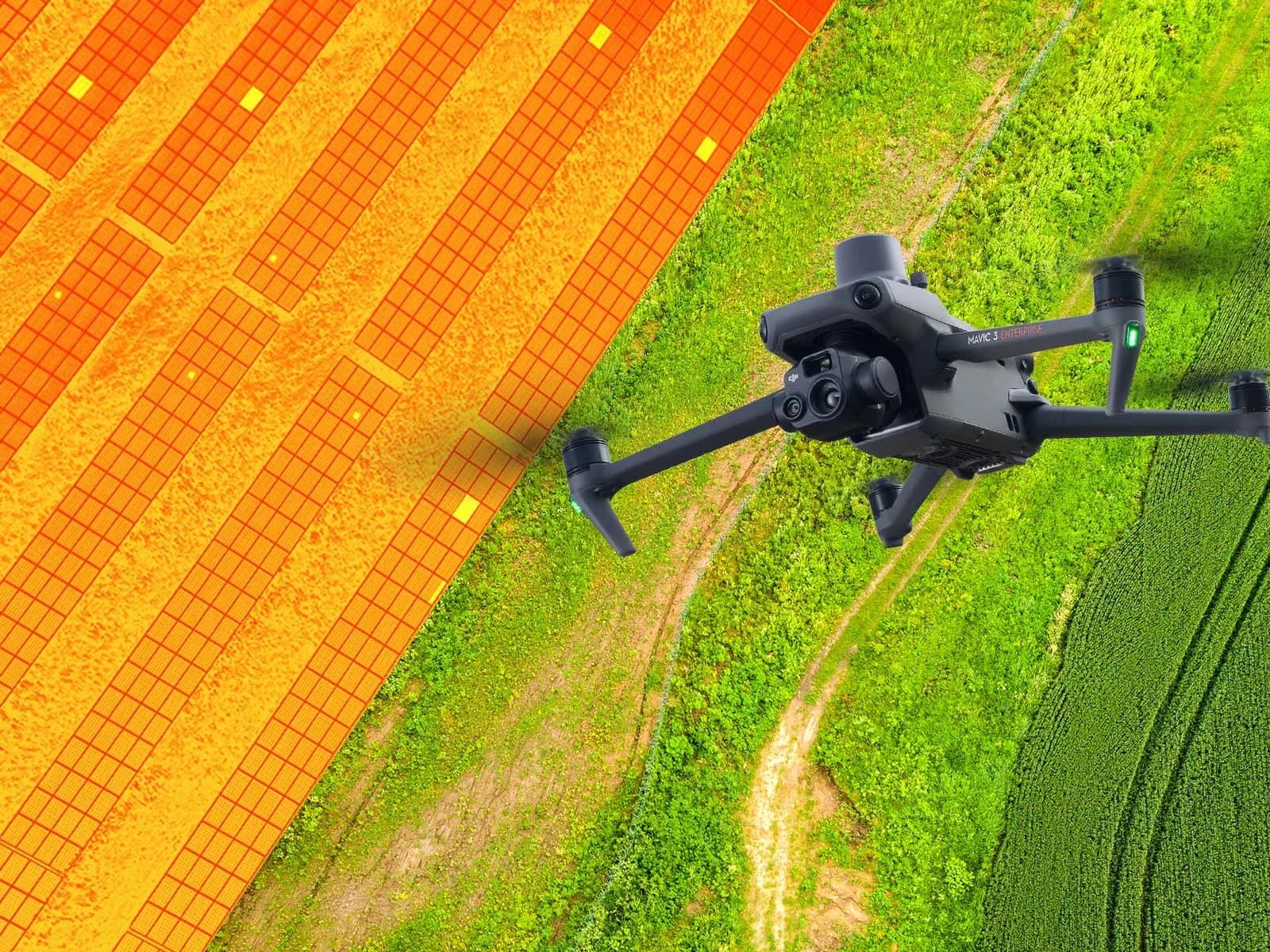
Aerial thermography records surface-temperature patterns across operating PV modules and related equipment using an infrared camera carried by a drone. The resulting images can show temperature differences between cells, modules, strings, connectors, and other components when the array is operating under conditions suitable for thermal inspection.
The camera does not directly measure electrical current, voltage, insulation resistance, or mechanical integrity. It records infrared radiation associated with the viewed surface, and that information is converted into temperature-related image data. The thermal pattern therefore needs to be interpreted together with the electrical configuration and the conditions present during acquisition.
On a large array, the main advantage is spatial screening. Instead of beginning with detailed ground measurements on every module, the inspection team can identify locations that behave differently from comparable parts of the plant and direct further investigation toward those areas.
Visible imagery can provide additional context. A module that appears thermally unusual may also show contamination, shading, broken glass, vegetation, or another visible condition that changes how the thermal image should be interpreted.
A thermogram is therefore an observation layer. It shows where temperature behavior differs; it does not automatically state why the difference exists.
Why Temperature Patterns Matter on an Operating Array
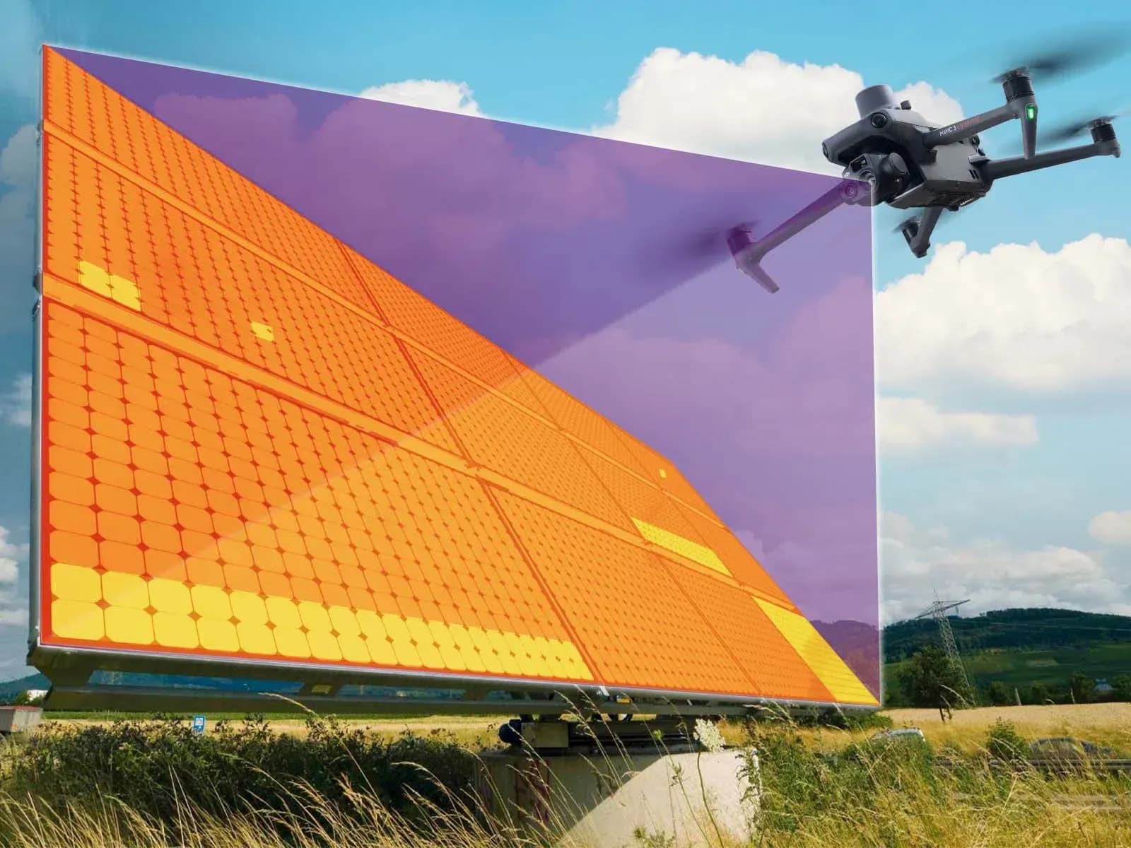
Electrical and physical conditions can affect how heat develops and spreads across PV equipment. A localized warm cell, a repeated pattern across part of a module, a connector operating warmer than comparable connections, or an entire string that behaves differently can all indicate that the location deserves closer inspection.
The significance of the pattern depends on the operating state. A module that carries current under stable irradiance can present different thermal evidence from the same module under low irradiance, rapid cloud changes, or a different electrical configuration. Temperature should therefore be evaluated as part of the operating context rather than as a stand-alone fault value.
Comparison is often more useful than an isolated absolute temperature. Modules of similar type, orientation, irradiance, and electrical state can provide a reference for identifying unusual behavior. The comparison becomes weaker when one row is shaded, one string is disconnected, or the environmental conditions change during the flight.
Some electrical problems may generate detectable heating, while others may not produce a clear surface-temperature difference during the inspection. A normal-looking module is therefore not proof that its insulation, current, voltage, connectors, or internal electrical condition are all satisfactory.
Temperature patterns matter because they narrow the search. Their role is to identify candidates for review, not to replace the measurements required to confirm the suspected condition.
Planning an Investigation
A thermographic investigation should begin with a defined question. The team may be screening the whole plant for module-level abnormalities, investigating a specific inverter or string, reviewing an area after an event, or checking whether a previous finding remains present. The objective determines how the flight should be planned.
Target resolution is a key decision. A survey intended to identify broad module-level differences can use a different altitude and image density from one intended to resolve smaller cell-level patterns. Flight height, lens, thermal resolution, speed, viewing angle, and target size need to be considered together.
The scope should identify which blocks, rows, modules, or electrical areas are included. It should also state what will happen if a section cannot be inspected because of obstacles, access limits, unsafe flight conditions, or poor imagery. Uninspected areas should remain visible in the final record.
Time of day and weather conditions matter because the array needs meaningful and sufficiently stable solar input for many thermal patterns to become interpretable. Wind, moving clouds, and rapidly changing irradiance can reduce comparability across a long survey.
IEC 62446-3 addresses outdoor thermographic inspection of operating PV systems, including equipment, environmental conditions, inspection procedure, personnel competence, and reporting. It does not prescribe one universal module-temperature range for every plant and should not be treated as a software detection algorithm.
Acquisition Conditions and Their Effect on Interpretation
Irradiance influences how much electrical current the modules can produce and therefore affects the thermal behavior associated with many operating abnormalities. Images collected during substantially different irradiance conditions should not be compared as though the array were under the same load.
Wind affects convective cooling. Strong or changing wind can reduce the temperature difference between an abnormal component and its surroundings, while calm conditions can allow more visible thermal contrast. Wind conditions are therefore relevant to both acquisition and later interpretation.
Cloud movement introduces another source of uncertainty. A module that has just entered or left shade may still be thermally responding to the change when the image is captured. If a drone moves across the plant while clouds are changing the irradiance, apparent differences between rows may reflect the environment rather than plant condition.
Module temperature should be recorded as part of the inspection context where relevant. It should not be turned into a universal pass/fail value because thermal behavior depends on module type, electrical state, irradiance, wind, geometry, and the specific observation being investigated.
Viewing angle also matters because PV glass reflects infrared radiation. The sky, terrain, nearby structures, vegetation, and the aircraft itself can create apparent hot or cool regions. Reflections should be considered before an unusual pattern is classified as an equipment finding.
From Imagery to Reviewed Findings
After acquisition, images need to be connected to physical locations. Row, string, block, module, or equipment references help the reviewer turn a thermogram into a finding that field personnel can locate. Large image collections without reliable location information create substantial review work but limited maintenance value.
The initial review should produce candidate observations rather than automatic diagnoses. A reviewer or software system may identify a localized elevated temperature, an unusual cell pattern, connector heating, or a module that differs from neighboring equipment. That candidate should then be checked against visible imagery, plant layout, operating data, and the acquisition conditions.
Artifacts need to be excluded where possible. Reflection, poor focus, unsuitable viewing angle, temporary shading, cloud transition, or insufficient resolution can create patterns that resemble equipment abnormalities.
AI-assisted analysis can help filter large datasets and identify images that deserve attention, but it should remain a candidate-generation step. Human review is needed before a finding is accepted, and direct electrical evidence may still be required before the cause is assigned.
The report should keep observation and diagnosis separate. Describing an elevated temperature pattern is different from confirming a damaged cell, failed diode, open circuit, or high-resistance connection.
What Follows a Thermal Finding
The next step depends on what the thermal observation suggests. A string-level difference may lead to current or voltage measurements, while a suspected connection problem may require physical inspection and direct electrical testing. A module-level pattern may lead to IV-curve testing, insulation testing, or another method chosen for the suspected mechanism.
The purpose of verification is to determine whether the thermal candidate corresponds to an actual electrical or physical condition. A maintenance decision should be based on that combined evidence rather than on the color scale of the thermogram alone.
Location and traceability remain important through this process. The original image, environmental conditions, module or circuit identifier, electrical follow-up, and maintenance action should be tied to the same record. This makes later inspection more useful and avoids rediscovering the same issue.
After corrective work, repeat thermography may help determine whether the previous thermal pattern remains present under suitable conditions. The repeat image should still be interpreted in context rather than treated as directly equivalent if irradiance, wind, module temperature, or viewing geometry differ substantially.
Limits
A thermal pattern does not prove root cause by itself. Similar temperature behavior can result from different electrical, physical, or environmental mechanisms, and some defects may produce little or no detectable thermal contrast during the survey.
One aerial thermography investigation is also not continuous monitoring. It records the plant during a defined time window. Intermittent conditions may be absent during the flight, and new problems can develop after the inspection.
Thermal data cannot directly verify polarity, insulation resistance, continuity, open-circuit voltage, short-circuit current, IV characteristics, or complete functional operation. When the maintenance decision depends on those properties, the appropriate electrical test remains necessary.
IEC 62446-3 provides a framework for outdoor thermographic inspection of operating PV systems through requirements and guidance relating to equipment, environmental conditions, procedure, personnel competence, and reporting. It does not transform a thermal image into an automatic conformity or safety decision.
Software can organize images, identify candidate findings, preserve location information, and support reporting. It cannot replace competent technical interpretation or the electrical measurements required to establish the condition of the plant.