
What Is a Thermal Drone?
What is a thermal drone? Learn how infrared drone cameras work, where they are used in solar inspection and what thermal imagery can and cannot show.
How Thermal Drones Work
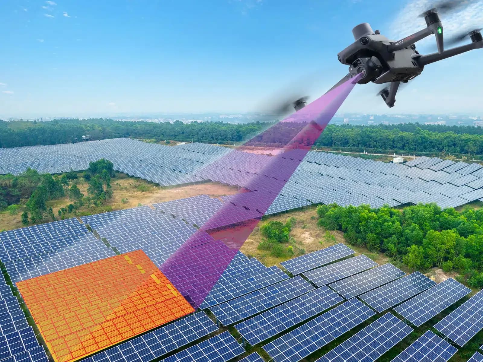
A thermal drone is an unmanned aircraft equipped with an infrared camera and the flight systems required to position that camera over or around a target. In PV inspection, the aircraft is used to collect temperature-related imagery across operating modules and selected electrical equipment.
The drone itself does not detect electrical faults. Its role is to move the sensor through a controlled route while preserving information such as location, altitude, orientation, and capture time. Flight stability and repeatability can improve the consistency of the resulting dataset.
The thermal camera observes infrared radiation from surfaces within its field of view. Depending on the camera and manufacturer specifications, the system may provide image data together with temperature measurements associated with pixels or selected areas.
Camera capability, flight height, lens, focus, viewing angle, target size, weather, and electrical operating state all influence what can be extracted from the image. A capable aircraft flown under poor conditions can still produce data that are difficult to interpret.
A thermal drone should therefore be understood as an acquisition system. Inspection quality comes from the combination of equipment, method, environment, review, and follow-up.
What Infrared Thermal Imaging Records
Infrared thermal imaging records radiation associated with the temperature and surface properties of the viewed object. The camera converts this information into an image that represents differences across the scene and, where supported by the equipment, can provide temperature measurements under defined conditions.
The image is not a direct map of electrical current or power. A hot region can result from several mechanisms, including electrical resistance, cell behavior, shading, environmental heating, or reflection. The cause must be evaluated separately.
Surface properties also matter. Emissivity, reflected radiation, distance, viewing angle, atmosphere, and camera settings can influence temperature measurement. Module glass is particularly important because reflective effects can produce apparent patterns that are not generated inside the module.
Thermal sensitivity, spatial resolution, and temperature measurement accuracy are separate characteristics. A camera that distinguishes small thermal differences does not automatically provide more precise absolute temperature measurement, and a sharper image does not automatically mean a more accurate temperature value.
The inspection procedure should therefore define what type of evidence is expected from the camera. A thermal image may be sufficient to identify a candidate, while a maintenance decision may require additional data.
Thermal Mapping on Solar Panels
Thermal mapping associates temperature-related imagery with the physical position of PV modules or other assets. This allows the reviewer to move from a site-wide survey to a specific row, module, connector, or electrical area that can be inspected on the ground.
Aerial thermography is well suited to large arrays because repeated module geometry can be screened systematically. A planned route can capture many rows under similar viewing geometry, provided environmental and operating conditions remain sufficiently stable.
Thermal mapping should preserve the original source imagery where detailed analysis is required. A stitched site-wide thermal representation can be useful for navigation and overview, but resampling, changing viewing angles, and image blending can affect the representation of individual measurements.
Location accuracy also has limits. GNSS quality, camera positioning, map alignment, terrain, and processing can shift the apparent location of a finding. The required precision should match the maintenance task.
Thermal maps therefore work best as a navigation and inspection-record layer. They help answer where an abnormal pattern was observed, while electrical tests and field inspection determine what the pattern means.
A map should never be treated as evidence that all unflagged modules are electrically healthy.
How Aerial and Ground Inspection Complement Each Other
Aerial inspection is efficient at finding exceptions across a large field. It can identify unusual thermal patterns, visible damage, vegetation, shading, or other conditions without requiring a technician to examine every module individually at the beginning of the survey.
Ground inspection provides the detail needed to verify those findings. Technicians can inspect connectors, junction boxes, cables, labels, mounting, seals, corrosion, and other features that may not be resolved clearly from the air.
Electrical measurements also require ground access. Voltage, current, insulation resistance, continuity, polarity, IV characteristics, and other circuit properties cannot be established solely from thermal imagery.
The two approaches therefore form a useful sequence. Aerial data narrows the problem, while ground methods determine the physical or electrical cause. This reduces the risk of sending technicians to every module without first knowing which locations deserve attention.
Ground thermography can also be useful when a component requires a closer angle or more controlled geometry than an aerial survey can provide. The inspection method should follow the technical question rather than treating one platform as universally superior.
Thermal Video, Temperature Data and Inspection Evidence
Thermal video can provide useful context by showing how a scene changes as the aircraft moves across a row or piece of equipment. It may help reviewers understand spatial relationships that are difficult to reconstruct from isolated still images.
Video should not automatically replace still thermal frames where detailed temperature review is required. Compression, motion, changing viewing angle, frame selection, and the way temperature data is preserved can affect what evidence remains available after the flight.
Temperature measurements should be kept with enough context to interpret them. The original image, module or equipment location, camera information, environmental conditions, viewing geometry, and time of capture may all matter when the finding is reviewed later.
Visible imagery can strengthen the record. A thermal candidate associated with contamination, broken glass, a shadow, or vegetation may be easier to interpret when the corresponding visible image is available.
Inspection evidence should therefore preserve the original measurement data and its context rather than only a colored thermal preview. A screenshot can be useful in a report but may not contain everything needed for later technical review.
Manufacturer documentation should be used to understand what temperature data the specific camera actually records and under what conditions its stated measurement performance applies.
Planning a Survey and Reading the Results
Survey planning begins with the target. If the team needs module-level screening, the required resolution and flight geometry differ from a survey intended to investigate smaller cell-level patterns or specific electrical components.
Environmental conditions must also support interpretation. IEC 62446-3 covers outdoor thermographic inspection of operating PV systems, including equipment, environmental conditions, procedures, personnel competence, and reporting. It does not define one universal temperature threshold for every array.
Irradiance influences electrical loading, wind influences cooling, and cloud movement can change conditions during the survey. Module temperature and viewing angle also matter, particularly when repeat inspections are compared.
During review, candidate observations should be checked against visible images, plant layout, monitoring data, and acquisition conditions. Reflections, shadows, low resolution, poor focus, or transient environmental changes should be considered before a finding is accepted.
The reviewer should then decide whether electrical or physical verification is required. Thermal data can identify where to look, but it should not be asked to answer questions it does not directly measure.
Limits
Thermal data is not a stand-alone diagnosis. A similar temperature pattern can arise from different causes, and some real defects can produce little or no detectable thermal contrast during the survey.
Comparison also becomes unreliable when acquisition conditions are not recorded. Two images of the same module taken under different irradiance, wind, module temperature, electrical loading, or viewing angle can look different even when the hardware condition is unchanged.
One drone flight is not continuous monitoring. It provides evidence from a limited period and cannot show intermittent faults that were inactive during the survey or problems that developed later.
Thermal imagery cannot directly confirm polarity, insulation resistance, current, voltage, continuity, IV characteristics, or full functional behavior. Those properties require their own electrical tests.
Software can organize imagery, map candidates, and support human review, but it does not turn thermal patterns into automatic fault diagnoses or safety decisions.