
Thermal Inspection of a 745 kW Photovoltaic Plant
Drone-based thermal and RGB inspection of the photovoltaic plant in Kaštel Sućurac, Croatia, covering 1,755 modules to identify thermal anomalies associated with external shading and support performance assessment and maintenance prioritization.
Hakan Yaralı · Technical Manager
Project at a Glance
- Plant capacity
- 745 kWp
- Modules inspected
- 1,755
- Inspection area
- ~0.418 ha
- Data captured
- Thermal + RGB
- Inspection duration
- 1 field day
- Suspected anomalies
- 581
- Location
- Kaštel Sućurac, Croatia
- Inspection date
- 2026-08
- Inspection standard
- IEC 62446-3 Compliant Thermographic Inspection
Project Context
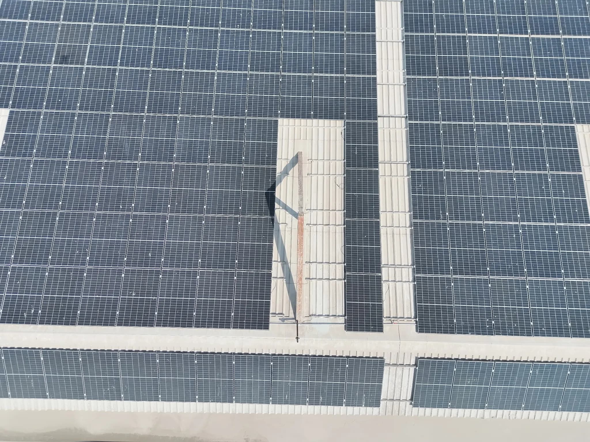
External shading was identified as a significant factor affecting the thermal behavior of the PV modules. In the most heavily shaded areas, the inspection revealed localized heating, hotspot formation, and diode-related anomalies, showing how external site conditions can directly influence module performance. By combining drone-based thermal and RGB imagery, the shaded areas could be evaluated together with their thermal response. This made it possible to identify the modules most affected by abnormal heating, assess the associated performance impact, and prioritize the areas requiring maintenance or corrective action.
Inspection Scope
What was inspected
- 1,755 Trina Varius photovoltaic modules included in the inspection scope
- Assessment of external shading intensity and distribution across affected modules
- Detection and classification of hotspot, cell, and diode-related thermal anomalies
- Evaluation of localized heating in modules exposed to persistent shading
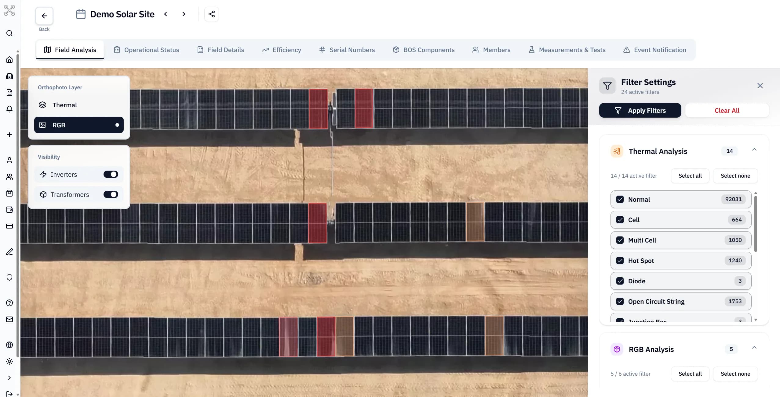
- Cross-assessment of thermal findings with RGB observations to evaluate the relationship between shading and abnormal thermal behavior
- Technical review of the most affected modules
- Prioritization based on estimated performance and operational impact
Methodology
- 1
Pre-flight planning
Flight altitude was defined to achieve a 3 cm/pixel GSD in accordance with IEC 62446-3 requirements, while overlap and flight route were planned according to the plant layout.
- 2
RGB and thermal data acquisition
Thermal and RGB imagery was captured across the inspected photovoltaic array.
- 3
Image quality control and alignment
Coverage and thermal image integrity were checked and imagery was georeferenced for analysis.
- 4
AI-assisted anomaly screening
Thermal patterns were detected, grouped and mapped to individual photovoltaic modules.
- 5
Technical review
Detected findings were reviewed and classified according to their thermal characteristics.
- 6
Reporting and verification plan
Prioritized findings were delivered to the client together with efficiency and loss-impact assessments to support subsequent maintenance activities.
Findings
| Finding | Detected pattern | Possible cause | Verification | Status |
|---|---|---|---|---|
| Hotspot | A localized area reaches an abnormally high temperature compared with its surroundings. | Cell damage, microcracks, physical defects, shading, contamination, or other conditions that cause abnormal localized heating. | Thermal measurement and visual inspection: reported; further field verification may be required. | Pending |
| Cell Fault | A PV cell loses normal function, causing localized heating and reduced performance. | Manufacturing defects, microcracks, physical damage, or deterioration of the affected cell. | Thermal measurement and visual inspection: reported; further field verification may be required. | Pending |
| Multicell Fault | Multiple PV cells within the same module lose normal function, causing wider performance and power loss. | Manufacturing defects, thermal stress, or physical damage affecting multiple cells within the module. | Thermal measurement and visual inspection: reported; further field verification may be required. | Pending |
| Diode Fault | Uniform heating across a module substring, indicating that the affected cell group is being bypassed. | Bypass diode short circuit or continuous conduction, causing current to bypass the affected substring. | Thermal measurement and visual inspection: reported; further field verification may be required. | Pending |
| Short Circuit Module | Abnormal heating across the module, indicating unintended current flow within the internal circuit. | An unintended conductive path between positive and negative poles, causing short-circuit behavior within the string. | Thermal measurement and visual inspection: reported; further field verification may be required. | Pending |
Thermal Evidence
Thermal image
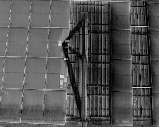
RGB image
Actions and Outcome
- A total of 581 suspected anomalies were identified and reported to the client.
- The highest concentration of thermal anomalies was observed in areas affected by external shading, where localized heating was more frequently associated with hotspot, cell, and diode-related faults.
- Modules exposed to persistent shading showed stronger thermal stress, making these areas a priority for detailed maintenance review and corrective action.
- The efficiency impact of the detected anomalies was assessed together with their estimated annual energy loss and financial impact.
- Findings were prioritized according to their estimated effect on plant performance, energy production, and financial loss, helping the client focus maintenance activities on the most critical shaded areas first.
Limitations
Thermal imagery can identify temperature patterns requiring investigation, but it does not independently confirm every electrical or mechanical root cause. Irradiance, wind, reflections, shading, soiling, flight conditions and equipment configuration may affect interpretation.
Other case studies
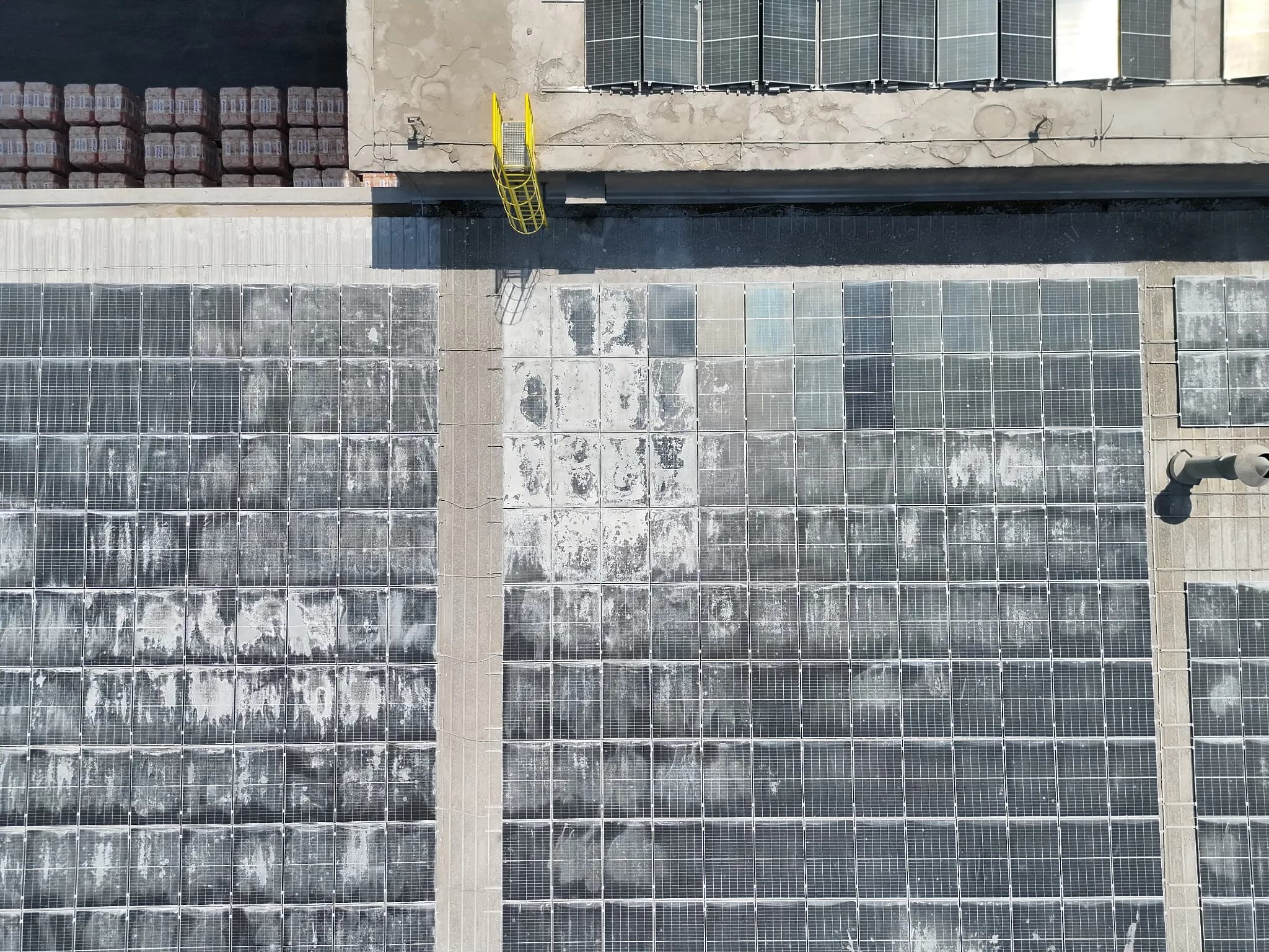
Thermal Inspection of a 462 kW Rooftop Solar Plant
Drone-based thermal and RGB inspection of a rooftop photovoltaic plant in Kaštel Sućurac, Croatia, covering 1,089 half-cut modules to identify thermal anomalies and support performance assessment and maintenance prioritization.
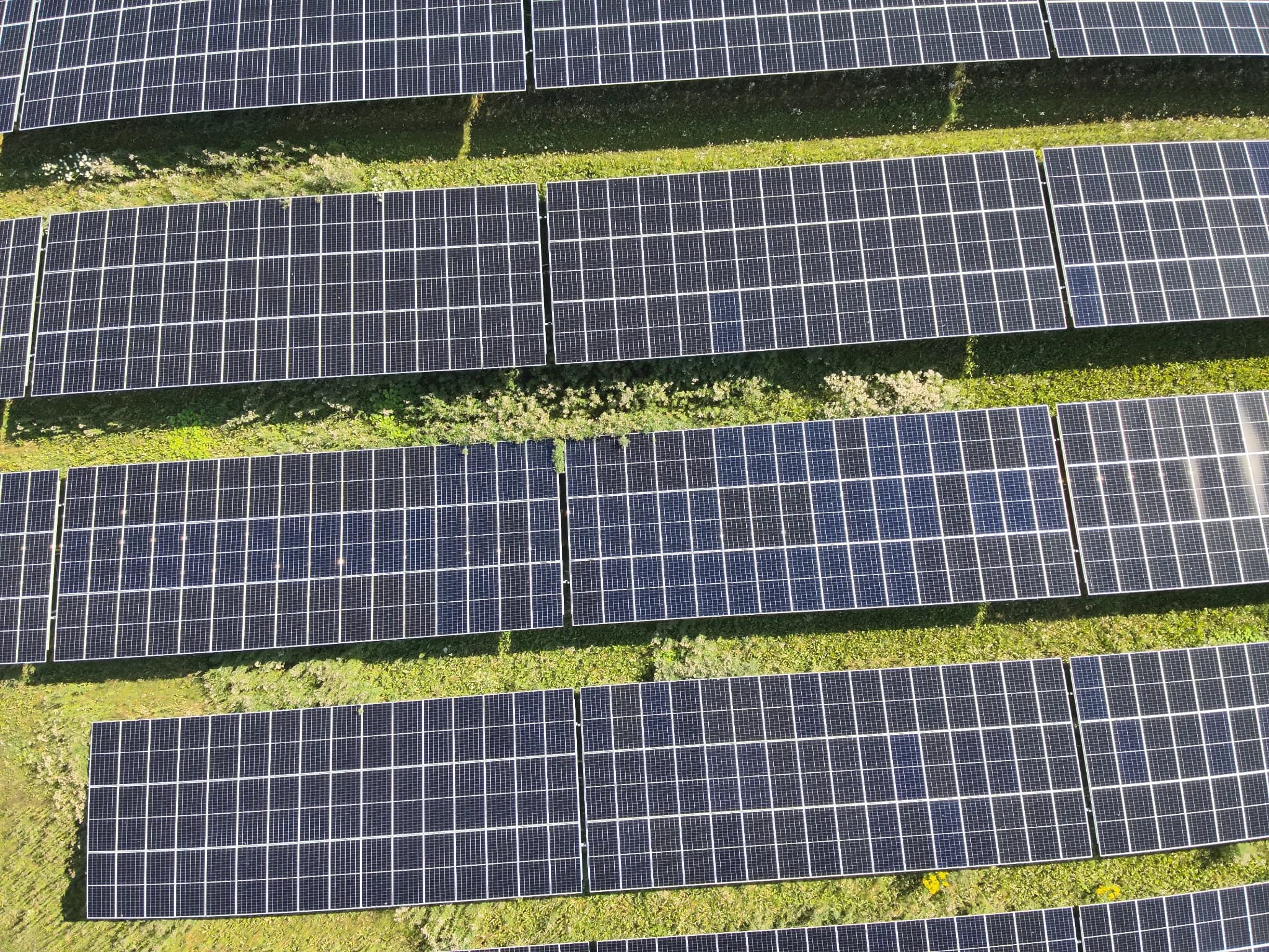
Thermal Inspection of a 30.54 MW Ground-Mounted Solar Plant
Drone-based RGB and thermal inspection of the solar plant in Borgdorf-Seedorf, Germany, covering 47,448 photovoltaic modules to identify and assess suspected thermal anomalies requiring maintenance attention.
Planning a photovoltaic inspection?
Share your plant capacity, module count and inspection objective to receive a proposed inspection scope.
Request an Inspection Scope