DJI Mavic 3 Thermal (M3T) Specifications for Solar Inspection
DJI Mavic 3 Thermal specs for solar inspection: thermal resolution, camera formats, configuration-dependent flight time, RTK and practical survey limits.
Why Specifications Alone Do Not Determine Inspection Quality
The DJI Mavic 3 Thermal, commonly referred to as the M3T, belongs to a class of compact enterprise drones that combines thermal and visible imaging for inspection work. For PV applications, its practical value depends on whether the complete acquisition system can produce the resolution, temperature information, location context, and repeatability required by the inspection procedure.
A specification sheet cannot answer that question by itself. Detector resolution, lens characteristics, thermal sensitivity, temperature measurement capability, visible-camera performance, positioning, and flight endurance all influence the workflow, but none independently guarantees useful PV findings.
Inspection quality also depends on flight height, speed, viewing angle, irradiance, wind, clouds, module temperature, focus, electrical state, and the experience of the reviewer. The same drone can produce very different results when those variables change.
Manufacturer specifications should therefore be treated as equipment limits and capabilities rather than as diagnostic claims. Any numerical camera, flight, environmental, positioning, or battery specification should be checked against the current manufacturer documentation for the exact model and configuration.
The important question is whether the equipment can support the defined PV inspection task under the actual site conditions.
Camera Detail and Operating Limits
Camera detail should be evaluated from the feature that needs to be resolved. A survey intended to identify module-level differences does not require the same spatial detail as one intended to distinguish smaller cell-level thermal patterns. The target size, lens, flight height, camera resolution, and viewing geometry work together.
Thermal sensitivity is another factor, but it should not be confused with temperature measurement accuracy. A camera may distinguish small temperature differences without making every absolute temperature value equally precise under all field conditions.
Operating limits also matter. Wind, ambient conditions, aircraft limitations, sensor operating range, and other restrictions should be taken from current manufacturer documentation rather than repeated from unverified secondary sources. These limits determine whether the aircraft can be operated, but they do not automatically determine whether the thermal conditions are suitable for PV inspection.
For example, a flight can be physically possible while the thermographic conditions are poor because irradiance is unstable or wind is suppressing useful thermal contrast. Aircraft limits and inspection limits are related but not identical.
A technical evaluation should therefore keep manufacturer equipment specifications separate from IEC 62446-3 inspection conditions and from site-specific aviation requirements.
Thermal and Visual Cameras on the M3T
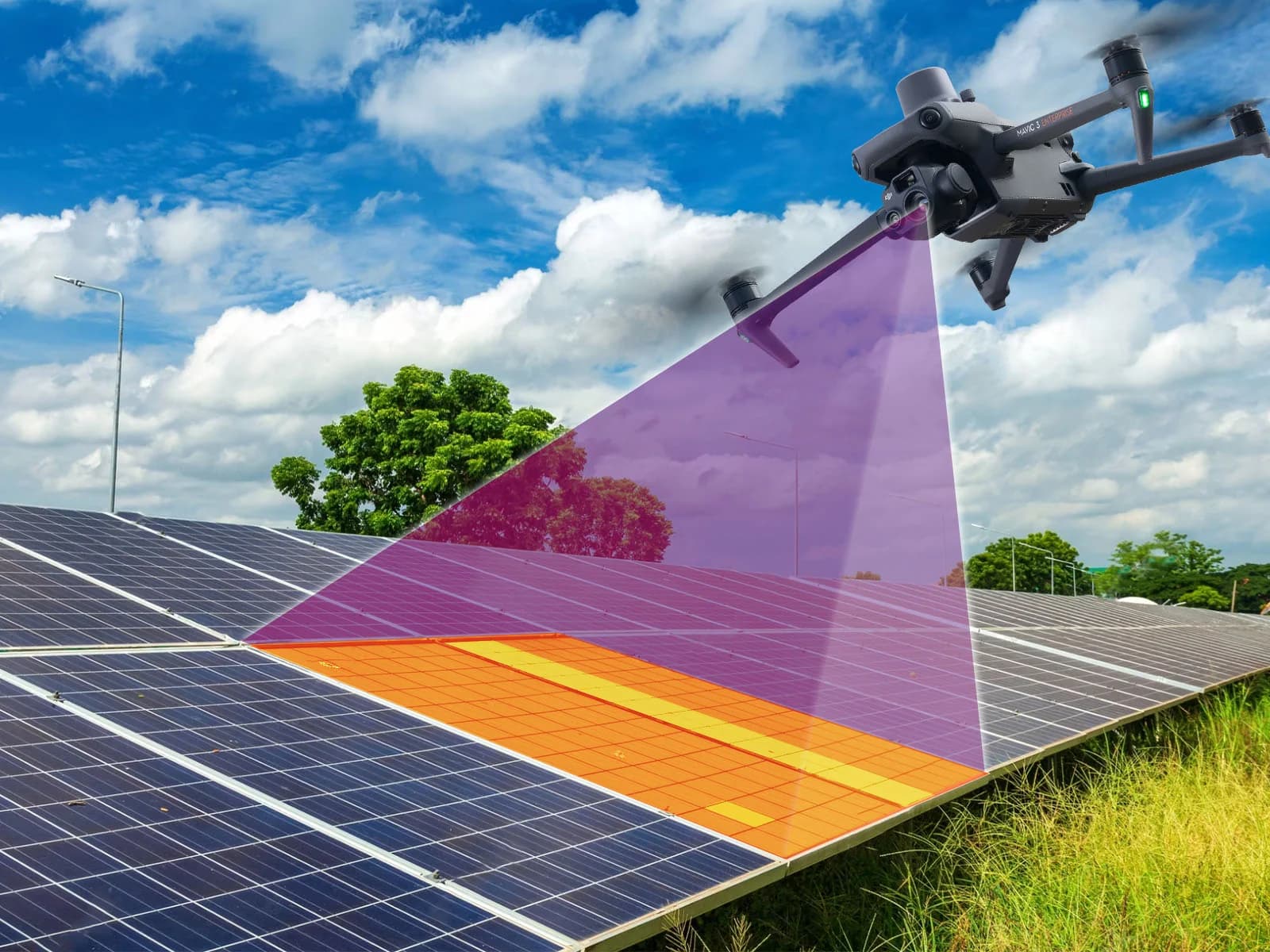
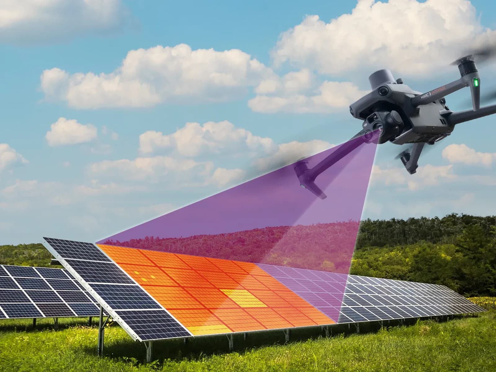
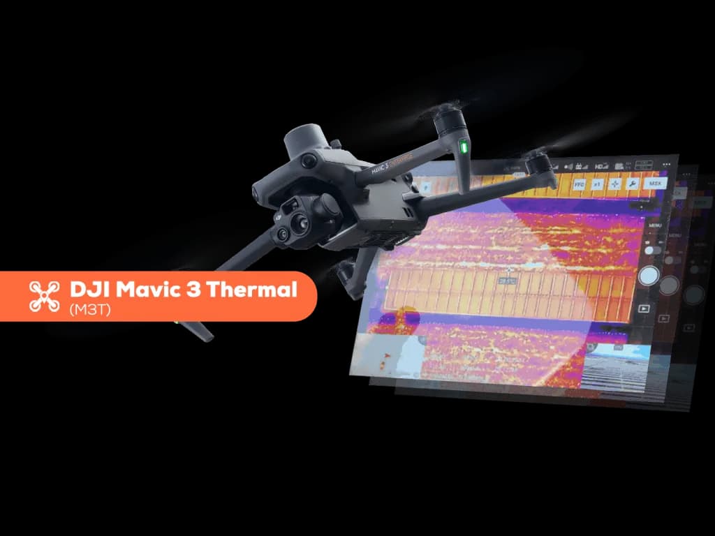
The M3T combines thermal and visible imaging capabilities according to the manufacturer's product configuration. For solar inspection, this allows thermal observations to be reviewed together with normal photographs that show module surfaces, rows, vegetation, shadows, structures, or other contextual features.
The thermal camera provides temperature-related data that can support identification of unusual module, cell, string, or connection patterns. The exact sensor characteristics, lens information, measurement range, measurement performance, and operating limits should be taken directly from current DJI technical documentation.
The visible camera performs a different role. It can provide higher-detail context for broken glass, contamination, physical damage, module position, labels, or shading conditions that may be difficult to interpret from thermal imagery alone.
Neither camera replaces electrical testing. A thermal observation cannot directly establish insulation resistance, polarity, voltage, current, continuity, or IV behavior, and a visible image cannot establish those properties either.
Using both cameras together can improve review because the same location can be examined through two different evidence types. The benefit comes from context and traceability rather than from treating either camera as an automatic fault detector.
Flight Time and RTK Relevance for Solar Sites
Flight endurance affects how much of a plant can be covered between battery changes, but practical survey duration should not be inferred from a single manufacturer endurance figure. Wind, route density, altitude, temperature, launch location, operating reserve, camera use, site geometry, and mission requirements can all change actual field time.
Manufacturer flight-time figures should therefore be used as reference specifications under their stated test conditions, not as guaranteed PV survey duration. Large plants may require several flight segments even when the aircraft has sufficient endurance for efficient operation.
RTK or other higher-precision positioning options can be relevant where better location consistency is needed. This can improve the ability to associate images with plant geometry or repeat routes, but positioning accuracy should still be evaluated as part of the complete survey workflow.
Higher positioning precision does not improve thermal measurement by itself. A module can be located very accurately while the thermal image remains unsuitable because of poor irradiance, reflections, wind, insufficient target resolution, or another acquisition problem.
For repeat inspections, route consistency can be useful, but environmental comparability remains necessary. Flying the same coordinates does not recreate the same electrical loading or thermal conditions.
The correct evaluation is therefore operational: does the positioning and endurance capability support the required inspection workflow on the actual site?
Using M3T Data with MapperX
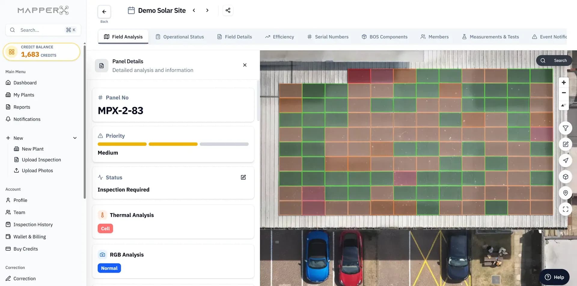
Data from an M3T-class inspection can be organized within MapperX to connect thermal and visible imagery with plant locations, candidate findings, inspection records, and later maintenance information. The purpose is to keep the evidence traceable from acquisition through review.
Images should first be associated with physical assets or reliable site positions. Row, block, string, module, or equipment references help reviewers and field teams understand where the observation occurred.
Candidate thermal abnormalities can then be reviewed alongside visible imagery, plant layout, monitoring data, and recorded environmental conditions. Automated or AI-assisted processing can help flag images that deserve attention, but candidate generation should remain separate from confirmation.
Human review is required to exclude reflections, shading, focus problems, cloud transitions, unsuitable geometry, or other artifacts. Where the maintenance conclusion depends on an electrical property, the relevant electrical test should then be performed in the field.
MapperX can support organization, review, comparison, and reporting. It does not make the aircraft more thermally accurate and does not replace electrical measurements, qualified interpretation, or an inspection body's technical responsibility.
Preserve Measurement Data, Not Only Thermal Previews
A colored thermal preview is useful for communication, but it may not preserve everything required for later technical review. Inspection workflows should retain the original source files and measurement information produced by the camera where those data are needed for temperature analysis.
Original files can preserve information that is lost when an image is exported, resized, compressed, screenshotted, or inserted into a report. The exact type of temperature and metadata stored by the M3T should be confirmed from DJI's current manufacturer documentation and the file format produced by the selected workflow.
Environmental context should be preserved separately as well. Irradiance, wind, cloud state, module temperature, date, time, route, camera geometry, and relevant site limitations may be necessary to interpret a thermal observation later.
Visible source imagery also has value. A thermal candidate that appeared convincing during the first review may later be explained by a shadow, contamination, reflection, or physical object visible in the corresponding normal image.
Processed mosaics and report graphics should therefore complement rather than replace original measurement files. The original evidence is especially important when repeat surveys or later technical review may be required.
The dataset should remain traceable from original acquisition to reviewed finding and any subsequent electrical confirmation.
Selection Limits
Choosing a thermal drone by one specification can create false confidence. Higher resolution, lower stated thermal sensitivity, longer endurance, or more precise positioning can each be useful, but none guarantees that faults will be identified more accurately in real PV inspections.
Diagnostic performance depends on the full workflow. Equipment, optics, target resolution, environmental conditions, route design, electrical loading, review quality, and follow-up verification all influence the final result.
IEC 62446-3 addresses outdoor thermographic inspection of operating PV systems through equipment, environmental conditions, procedures, personnel competence, and reporting. It does not name one universally superior drone model or camera specification.
Before selecting a platform, representative datasets from conditions similar to the intended inspection are more informative than specification comparisons alone. Reviewers should examine whether modules and relevant thermal features are actually resolved, whether temperature data is preserved, and whether visible imagery provides enough context.
Manufacturer claims and technical specifications should be checked against current official documentation for the exact model. Unverified values from resellers, older product pages, or secondary comparisons should not be used as design assumptions.
Feature superiority is not diagnostic superiority. The appropriate platform is the one that produces reviewable evidence at the required resolution under the site's actual conditions and fits the broader inspection workflow.