
How to Detect Broken Solar Panels?
How to detect broken solar panels: observe the panels regularly, check glass, frame and junction box, then use thermographic inspection to find fractures.
What Counts as a Broken or Damaged Module
A broken solar module is not limited to one with visibly shattered glass. Damage can affect the front glass, frame, backsheet, junction box, connectors, cables, internal cell structure, or electrical insulation while leaving other parts of the module apparently intact. The inspection method should therefore match the type of damage being investigated.
Some damage is immediately visible after hail, impact, installation work, transport, or other mechanical events. Other conditions develop gradually through environmental exposure, moisture, movement, repeated temperature changes, or deterioration of electrical connections. A module can also contain internal damage that is difficult to identify from a normal photograph.
Physical damage and electrical failure should be kept separate during the first stage of inspection. Broken glass is a direct physical finding, but it does not by itself state how much electrical performance has changed. Likewise, an electrical abnormality does not necessarily mean the front glass or frame is visibly damaged.
The useful question is therefore not simply whether a panel looks broken. The team needs to establish what part is damaged, whether the condition affects electrical operation or insulation, and whether the module can remain in service while further verification is performed.
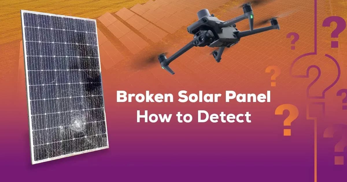
Visible Detection: Glass, Frame and Junction Box
Visible inspection should begin with the parts of the module that can be assessed without disturbing energized connections. Cracked or shattered glass, displaced frames, bent mounting interfaces, damaged backsheets, loose junction boxes, exposed conductors, and damaged connectors are findings that can be documented directly.
Glass damage can range from a small impact point to extensive cracking across the module surface. The electrical consequence cannot be determined from appearance alone because crack depth, moisture exposure, internal cell damage, and the condition of the laminate may differ between modules that look similar from a distance.
Frames should be checked for deformation, separation, impact marks, or mechanical stress that may affect module support. A displaced frame or mounting point can also change how loads are transferred into the structure. Mechanical assessment may therefore be required separately from the electrical condition of the module.
The junction box deserves specific attention because it contains electrical connections that are normally protected from the environment. Damage, loose attachment, cracked housings, missing seals, or visible signs of water entry can justify electrical verification before the module is returned to normal service.
Water marks, staining, corrosion, or contamination around cable entries and junction boxes should be recorded as observations. These signs may indicate moisture exposure, but visual evidence alone does not prove that insulation resistance has fallen below an acceptable level.
Preventing Further Damage and Risk
Inspection work should avoid turning a limited defect into a larger one. Walking on modules can damage glass, cells, frames, or mounting components, and should not be used as a routine way to reach a suspected problem. Access should follow the plant's approved maintenance routes and work procedures.
Damaged DC equipment also requires care because PV circuits can remain energized whenever sufficient light is present. Disconnecting a module or opening a connector under load can create a DC arc if the component is not intended for load breaking. A visible defect is therefore not a reason to bypass the site's isolation procedure.
Temporary measures may be appropriate when a damaged area needs to be secured before permanent repair. The exact action depends on the electrical state, physical condition, weather exposure, and plant design. Temporary work should not hide the original finding or create a new unverified connection.
Competent personnel should determine whether the affected circuit needs to be isolated, monitored, tested, or removed from service. A broken cover, cracked glass, or damaged junction box can have different consequences depending on whether energized parts, insulation, water ingress, or structural integrity are involved.
The inspection record should preserve the condition before intervention where this can be done safely. That makes it easier to distinguish the original damage from changes introduced during repair.
Thermographic Inspection with Aerial Drones
Aerial thermography can help identify modules whose surface temperature patterns differ from comparable modules while the PV plant is operating. A drone can screen many rows from above and direct attention toward localized hot areas, cool modules, repeated cell patterns, or broader differences between strings.
The method is particularly useful when visible damage is difficult to find across a large site or when monitoring data identifies an electrical area without identifying a specific module. Thermal imagery can narrow the search to a smaller set of candidates for ground-level verification.
IEC 62446-3 addresses outdoor thermographic inspection of operating PV systems. Its scope includes equipment, environmental conditions, inspection procedure, personnel competence, and reporting. It does not define a software algorithm or impose one universal module-temperature range for every installation.
Acquisition conditions matter. Irradiance, wind, cloud movement, module temperature, reflections, and viewing angle can affect the observed pattern. Flight height and camera characteristics must also provide enough spatial detail for the intended target; a broad module-level survey may not resolve a smaller cell-level feature.
Aerial thermography should therefore be used as a structured inspection method rather than as a simple photograph of heat. The value of the image depends on how it was captured and how carefully it is compared with the plant's operating context.
What Thermal Evidence Does and Does Not Prove
A localized thermal abnormality shows that one area is behaving differently from an appropriate comparison area under the conditions present during the inspection. That may justify investigation of cell behavior, shading, electrical connections, bypass-diode operation, physical damage, or another condition.
It does not prove root cause by itself. Similar thermal patterns can arise from different mechanisms, and environmental or geometric effects can imitate an equipment problem. Reflection from module glass is one example that can create apparent hot or cool areas without an internal defect.
A normal-looking thermogram has limits as well. Some damaged modules may not develop a detectable temperature difference during the flight, particularly if irradiance is weak, wind is strong, electrical loading is low, or the defect is intermittent.
Thermal evidence should therefore be described before it is diagnosed. "Localized elevated temperature on one cell area" is a defensible observation. Calling the same image a confirmed cracked cell, failed diode, or high-resistance connection requires additional supporting evidence.
One thermal survey is also not continuous monitoring. A condition may appear after the flight or disappear temporarily before the module is inspected.
When Electrical Testing Is Needed
Electrical testing is needed when the maintenance decision depends on a property that imagery cannot establish directly. An IV-curve measurement can show how a module or string behaves across a range of voltage and current, making it useful when the suspected condition concerns electrical performance or mismatch.
Insulation resistance testing is relevant when physical damage, moisture ingress, cable damage, or another condition raises questions about electrical isolation. A module can look visually intact while having an insulation problem, and a visibly damaged module may still require measurement to determine whether its insulation path has been affected.
Protective continuity testing answers a different question. Where exposed conductive parts and bonding arrangements are involved, continuity measurement can confirm whether the intended protective path remains electrically connected after damage or repair.
Other tests may be appropriate depending on the suspected condition. Voltage, current, polarity, connector examination, or component-level measurements can provide evidence that thermal or visible inspection cannot.
These tests do not replace one another. The field team should choose the measurement that corresponds to the suspected failure mechanism rather than running unrelated tests without a defined question.
Electrical testing also requires suitable isolation, instruments, and competent personnel. The presence of a thermal image does not reduce those requirements.
AI-Assisted Review and Human Confirmation
AI-assisted image review can help reduce the workload created by large aerial datasets. A system can flag images or module locations that differ from surrounding equipment, group similar patterns, or produce candidate findings for an inspector to examine more closely.
Those candidates should not be treated as automatic diagnoses. An image model may identify a region that resembles a hotspot, damaged surface, unusual module pattern, or another predefined category, but the classification still depends on image quality, environmental conditions, training data, and the context available to the reviewer.
Human review remains necessary to decide whether a candidate is a real observation, an artifact, or an expected operating condition. Reflections, shadows, cloud transitions, poor focus, insufficient resolution, and unusual plant geometry can all produce misleading candidates.
Confirmed findings should then be tied to a physical location and, where required, supported with electrical or ground-level evidence. The record should distinguish between the original candidate, the inspector's review, any follow-up measurement, and the final maintenance decision.
AI-assisted review can therefore help prioritize attention within a large dataset. It does not replace electrical testing, qualified inspection, or the responsibility to verify a condition before repair or replacement is specified.