
How to Inspect Solar Power Plants with Drones
How to inspect solar power plants with drones: plan from safe flight and thermal capture to mapped anomalies, field verification and work orders.
Why Drone Inspection Is Used
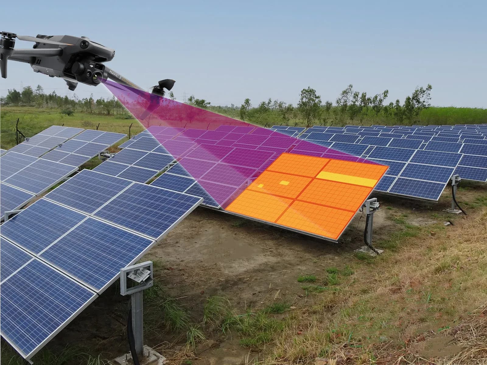
Drone inspection gives an O&M team a way to screen large PV areas before sending technicians to every row. Visible and thermal cameras can document module surfaces, row geometry, vegetation, shading, damaged components, and temperature patterns while preserving location information that helps technicians return to the correct part of the plant.
The main advantage is coverage rather than automatic diagnosis. A planned aerial route can collect data across many modules with more consistent camera geometry than an improvised walk through the array. This is especially useful on large ground-mounted plants where manual row-by-row screening requires substantial field movement.
Thermal imaging adds information that normal photography cannot provide. Localized heating, unusual module patterns, connector heating, or differences between comparable strings may identify areas that deserve further investigation. Visible imagery can then provide context such as broken glass, contamination, vegetation, shadows, or displaced equipment.
The value depends on the site. Small arrays, restricted airspace, difficult weather, insufficient thermal conditions, or extensive ground-level verification may reduce the practical advantage of using a drone. The aircraft should be selected because it fits the inspection objective, not because aerial inspection is assumed to be preferable in every case.
Drone Inspection Step by Step
The first step is to define the inspection question. A survey intended to document visible storm damage has different acquisition requirements from one intended to resolve cell-level thermal patterns. The scope should identify the blocks, rows, modules, or equipment to be covered and what follow-up is expected if an abnormality is found.
Flight permissions, site procedures, airspace constraints, obstacles, launch areas, and weather should then be checked. Flight height, route, speed, camera angle, target resolution, and image density are selected from the inspection objective. Areas that cannot be captured safely or reliably should be treated as limitations rather than silently included as inspected.
Before thermal acquisition begins, operating and environmental conditions need to be suitable. IEC 62446-3 addresses outdoor thermographic inspection of operating PV systems, including equipment, environmental conditions, inspection procedure, personnel competence, and reporting. It does not prescribe one universal module-temperature range and should not be treated as a drone flight algorithm.
During the flight, thermal and visible data are collected together with relevant location and flight information. After landing, the dataset is transferred, organized by plant location, checked for missing or poor-quality imagery, and reviewed for candidate findings.
The final stages are technical review and reporting. Candidate observations are separated from reflections, cloud transitions, poor focus, shading effects, or other acquisition artifacts. Findings that require electrical confirmation are then sent for the appropriate field test before a maintenance conclusion is made.
Compared with Traditional Ground Inspection
Ground inspection and drone inspection solve different parts of the problem. A technician on foot can examine connectors, labels, cable routing, mounting details, junction boxes, and other components at close range. The same technician can also perform electrical measurements that are impossible from the air.
Drone inspection provides broader initial coverage. It can identify where visible or thermal differences occur without requiring the field team to begin with detailed examination of every module. On large sites, this can reduce unnecessary walking and help prioritize the locations that deserve ground access.
Ground inspection remains stronger when the question requires physical interaction. Connector condition, insulation resistance, polarity, continuity, voltage, current, torque-related checks, and component replacement still require direct access and an appropriate electrical procedure.
Aerial imagery also has geometric and environmental limitations. Reflections, viewing angle, insufficient resolution, wind, cloud movement, and variable irradiance can affect interpretation. A person standing beside the equipment can sometimes resolve ambiguity that remains in an aerial image.
The practical workflow is therefore usually complementary. Aerial screening identifies where to look, while ground inspection and electrical testing establish what is actually wrong and what action is justified.
Thermal Review and Predictive Maintenance
Thermal review can help identify changes before they become obvious in plant-level production data, but the term predictive maintenance should be used carefully. A thermal pattern may indicate that a component is behaving differently from comparable equipment, yet it does not automatically predict when or whether that component will fail.
Historical thermal records can still be useful. If the same module, connector, or string location repeatedly shows an abnormal pattern under comparable conditions, the maintenance team has stronger evidence that the condition deserves investigation. Records of corrective work can then be connected to later inspections.
AI-assisted review may help filter large datasets by flagging candidate modules or image regions for human inspection. Candidate generation should remain separate from diagnosis. A model can identify a pattern that resembles a hotspot or string irregularity, but reflections, shading, acquisition artifacts, and normal operating differences still need to be excluded by a reviewer.
One inspection is not continuous monitoring. An intermittent fault may not be present during the flight, and a new condition can develop afterward. Monitoring data, event-driven inspections, and maintenance history remain important between surveys.
Thermal information therefore contributes to condition-based maintenance by improving where attention is directed. It should not be presented as a guarantee of future failure detection or as a substitute for direct verification.
Measuring the Outcome of Corrective Work
A repeat inspection can be useful after repair when the original finding was visible thermally or physically. The purpose is to determine whether the observed condition changed after the corrective action, not merely to produce another image of the same location.
Comparison requires similar acquisition conditions. Irradiance, wind, cloud state, module temperature, viewing angle, flight height, camera configuration, and electrical operating state can all affect the apparent thermal pattern. A lower temperature difference after repair is difficult to interpret if the second flight occurred under substantially weaker loading.
The same physical location should also be documented reliably. Module, row, string, or equipment identifiers allow the team to compare the correct asset instead of relying on approximate visual matching between flights.
Where the original problem was electrical, repeat electrical measurements may be more important than the thermal image. A repaired connector can be examined thermally, but the required verification may also include direct inspection or an appropriate electrical test depending on the work performed.
The closure record should state what was repaired, how the result was checked, and whether any limitation affected the comparison. This makes the follow-up useful to future O&M teams rather than reducing it to a before-and-after image pair.
A Practical Inspection Checklist
A practical drone inspection starts with scope, location, and objective. The team should know which plant areas are included, what level of detail is required, which environmental conditions are needed, and what types of finding will trigger ground verification.
Before flight, the team should confirm site access, airspace and operating constraints, weather, equipment readiness, camera settings, target resolution, route, and safe launch and recovery areas. For thermography, irradiance, wind, cloud conditions, and module operating state should be considered before data collection starts.
During acquisition, reviewers need enough information to trace images back to plant assets. Location metadata, visible context, thermal data, route information, and records of skipped or inaccessible areas should be preserved.
After the flight, image quality should be checked before detailed analysis begins. Blurred frames, strong reflections, cloud transitions, incomplete coverage, or insufficient resolution can produce false confidence if they are not identified early.
Candidate findings should be reviewed against visible imagery, plant layout, monitoring data, and acquisition conditions. Electrical tests or ground inspection should then be assigned where the maintenance decision depends on properties that aerial imagery cannot establish.
The report should document observations, verified findings, limitations, follow-up requirements, and any areas that were not reliably assessed.
Limits
Thermal data does not prove root cause by itself. A hot cell, connector, module region, or unusual string pattern can result from several electrical, physical, or environmental mechanisms. Similar-looking thermograms can therefore require different maintenance responses.
A drone also cannot directly verify insulation resistance, polarity, open-circuit voltage, short-circuit current, protective continuity, IV behavior, or complete functional performance. Those properties require suitable electrical instruments, procedures, and competent personnel.
Visible imagery has similar boundaries. It can document physical conditions but cannot prove that the underlying electrical circuit is healthy. A visually normal module may still have an electrical defect that requires another test method.
IEC 62446-3 provides a framework for outdoor thermographic inspection of operating PV systems, covering equipment, environmental conditions, procedure, personnel competence, and reporting. It does not make a drone or software platform a complete inspection system.