
What Is Photovoltaic (PV) Technology?
What is photovoltaic technology? Learn how PV cells convert sunlight into electricity, how solar modules work and the main components of a PV system.
What Photovoltaic Technology Is
Photovoltaic technology converts sunlight directly into electrical energy using semiconductor materials. When light reaches a PV cell, absorbed photons can create charge carriers that are separated by the cell's internal electric field, producing a DC voltage and allowing current to flow through an external circuit.
A single cell produces limited voltage and current, so cells are interconnected to form modules. Modules are then connected into strings and arrays to produce the electrical characteristics required by the system design. Inverters convert the DC output into AC where the installation supplies AC loads or connects to an AC grid.
PV systems contain more than modules and inverters. Cabling, connectors, mounting structures, combiner boxes, protection devices, earthing arrangements, monitoring equipment, disconnecting devices, meters, and control systems can all form part of a plant.
The electrical output changes continuously with solar conditions and operating temperature. For that reason, plant assessment requires context rather than treating one power value as a permanent property of the installation.
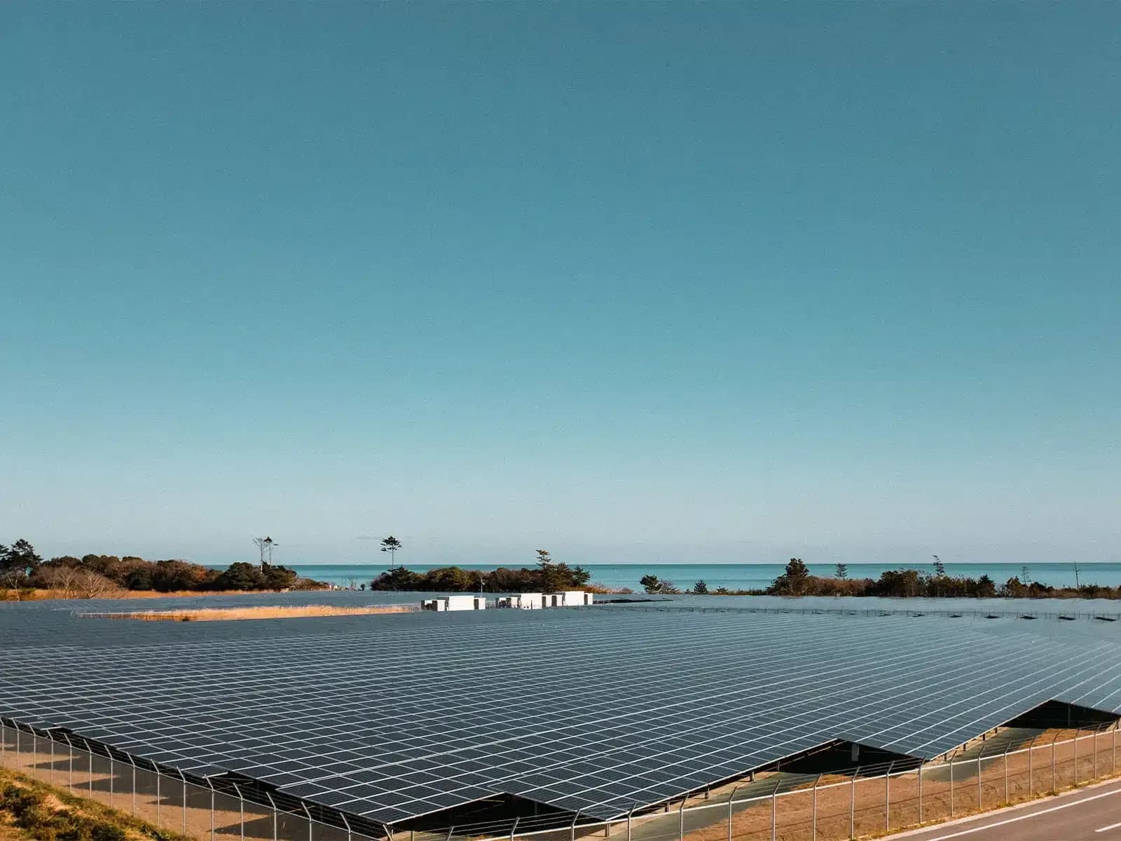
From Cell to Module to Array
Cells in a module are electrically interconnected so their individual voltage and current contributions can be combined. Modules can then be connected in series to increase string voltage and in parallel to increase current capacity, according to the inverter and system design.
Series connection means the electrical behavior of one part of the circuit can influence the rest of the string. If one module or cell group is severely shaded or electrically constrained, current through the series path may be affected. Bypass diodes can alter how parts of a module behave under certain conditions, but they do not remove every consequence of mismatch or damage.
At array level, many strings may feed combiner equipment or separate inverter inputs. Correct string length, polarity, conductor sizing, connector condition, protection, and equipment ratings are therefore important because the plant is built from repeated circuits that interact with downstream equipment.
The idea of the "weakest link" is useful only when applied carefully. A single abnormal component can influence the output of connected equipment, but the exact effect depends on circuit topology, bypass behavior, inverter architecture, shading, and operating conditions.
Understanding the hierarchy from cell to array helps with fault location. A cell-level thermal pattern, a module voltage difference, a string current deviation, and an inverter alarm describe different levels of the same electrical system.
What Changes Photovoltaic Output
Irradiance is one of the main factors affecting PV output. More incident solar energy generally allows the array to produce more current, while clouds, shading, solar angle, and atmospheric conditions can reduce the available irradiance. Measurements should therefore be interpreted against the conditions present at the time.
Module temperature also affects electrical behavior. For crystalline-silicon modules, increasing cell temperature at comparable irradiance generally reduces voltage and can reduce available power. The effect should be evaluated using the characteristics of the installed module rather than a universal temperature assumption.
Shading can affect individual cells, parts of modules, entire strings, or larger sections of the array depending on its source and geometry. Trees, structures, adjacent rows, dirt accumulation, snow, vegetation, or temporary objects can all change the irradiance reaching the active cell area.
Soiling has a similar site-specific effect. Dust, pollen, bird contamination, agricultural residue, and other deposits can reduce the light reaching cells, but the practical impact depends on coverage, distribution, module angle, weather, and local cleaning patterns.
Electrical condition matters as well. Open circuits, high-resistance connections, damaged connectors, blown fuses, inverter limitations, insulation faults, and other problems can change plant behavior independently of available sunlight.
Why Operating PV Systems Need Inspection
PV plants operate outdoors for long periods and contain large numbers of repeated components and connections. Weather, thermal cycling, moisture, contamination, mechanical movement, animals, vegetation, maintenance work, and electrical loading can change the condition of equipment after commissioning.
Monitoring systems provide useful operational information, but they do not reveal every physical defect. An inverter may report aggregate power while a localized connector, module, or bonding problem remains difficult to identify from plant-level data alone.
Inspection helps connect electrical behavior with physical equipment. Visual checks can reveal mechanical or environmental conditions, electrical tests can verify specific circuit properties, and thermography can show temperature patterns associated with operating abnormalities.
Different inspection methods should therefore be selected according to the question being asked. Insulation resistance testing examines electrical isolation, polarity testing verifies conductor orientation, current and voltage measurements describe circuit behavior, and functional tests check whether defined equipment functions respond correctly.
Inspection does not mean that every observed difference is a fault. Results need context, comparison, and, where necessary, follow-up measurements before a cause is assigned.
How Thermal and Electrical Evidence Differ
Thermography records infrared radiation associated with surface temperature. In an operating PV system, it can reveal relative temperature patterns across cells, modules, connectors, conductors, and other components when acquisition conditions are suitable.
Electrical tests measure different properties directly. Current, voltage, insulation resistance, continuity, and polarity each answer a narrower electrical question. A thermal pattern may identify where to investigate, while an electrical test may help determine whether a circuit characteristic is outside the expected condition.
The two evidence types are complementary rather than interchangeable. A connector can have an abnormal temperature pattern that leads to a resistance or connection check, while an insulation fault may be detected electrically without producing a useful thermal signature.
IEC 62446-3 concerns outdoor thermographic inspection of operating PV systems. It addresses equipment, environmental conditions, procedure, personnel competence, and reporting, and it does not impose one universal module-temperature range across all plants.
Thermal findings should be interpreted with irradiance, wind, cloud conditions, module temperature, reflections, viewing angle, and electrical operating state in mind. A hot region alone does not prove a specific root cause.
Electrical evidence also has limits. A normal voltage or current value does not prove that every part of the string is free from mechanical, thermal, or insulation-related problems.
Batteries, Storage and Grid Connection
A PV system does not require a battery in order to operate. Grid-connected systems can send available power through an inverter to local loads or to the electrical network according to the system design and applicable connection arrangement.
Battery storage can be added where the project requires energy shifting, backup capability, control of export, or another storage function. The battery system introduces its own power electronics, protection, controls, operating limits, and maintenance requirements. It should therefore be treated as a separate subsystem rather than assumed to be part of every PV plant.
Off-grid installations may use storage because generation and demand occur at different times and there is no grid connection to balance them. The required architecture depends on the load, generation profile, storage design, backup strategy, and operating objective.
Grid-connected PV also depends on inverter and protection functions. Voltage, frequency, synchronization, anti-islanding behavior, control settings, and monitoring can form part of the plant's operating requirements depending on the installation.
The presence of a battery does not eliminate the need to inspect the PV array itself. Modules, strings, cabling, connectors, mounting, protection, and inverter-side equipment still require condition assessment according to the maintenance plan.
Limits
No single inspection method describes the complete state of a PV plant. Monitoring may identify an operational deviation without locating it physically, while visual inspection can find damage that has not yet created an obvious electrical signal.
A single inspection is also not continuous monitoring. Conditions can change after the visit, intermittent faults may not be active during testing, and weather-dependent effects may appear only under particular operating conditions.
Thermal imaging has specific limits. It can show temperature differences associated with cell, diode, connection, string, or other operating conditions, but a thermal image alone does not prove root cause. Electrical or physical verification may be required before a defect is classified.
Likewise, a normal thermal image does not establish that insulation, polarity, grounding, current behavior, or every connection is correct. Those questions require the appropriate electrical or mechanical checks.
IEC 62446-3 provides a framework for outdoor thermographic inspection of operating PV systems, including equipment, environmental conditions, procedure, personnel competence, and reporting. It is not a software algorithm and does not define one fixed temperature criterion for all installations.